Operation of Oil-Flooded Screw Compressor Explained
Category > Oil and Gas
Apr 25, 2025BEFORE YOU READ: This post focuses exclusively on the application of oil-flooded screw compressors in the oil and gas industry. It does not cover other compressor types (such as rotary vane, reciprocating, dry screw, etc.) or other applications (like refrigeration, power generation, air compression, etc.).
Oil-flooded rotary screw compressors provide a reliable and efficient solution for gas compression across a wide range of applications in the oil and gas industry. These applications include, but are not limited to:
Vapor Recovery: Capturing vapors from low-pressure vessels like heater treaters, vapor recovery towers (VRT), or atmospheric storage tanks and compressing them into the gas sales line. Without compression, these vapors lack sufficient pressure to enter the sales line and would need to be flared or vented, resulting in both environmental harm and lost revenue from valuable rich gas.Boosting: Large gas pipelines operate at high pressures (1000–5000 psig), typically handled by multi-stage reciprocating compressors. However, these recips require stable, high suction pressures. Screw compressors excel at stabilizing fluctuating inlet pressures from production wellsites and boosting gas to the required suction pressure for recips, making them ideal for this intermediate role.Wellhead Compression: Installing a compressor between the wellhead and sales line reduces backpressure on the wellhead, increasing hydrocarbon flow rates. This can also help remove accumulated liquids in shut-in wells, kick-starting production.
Typical rotary screw compressors operate with suction pressures ranging from 0 to 50 psig and discharge pressures up to 350 psig. This post dives into the technical details of oil-flooded screw compressor operations, specifically tailored for operators—whether you're renting or purchasing the unit. Designed for customer operators, this guide provides practical insights into the working mechanism, key vessels and components, P&ID (Piping and Instrumentation Diagram), flow control strategies, and common maintenance issues. By the end, you'll have a solid understanding of the essential technical knowledge needed to operate screw compressors effectively.
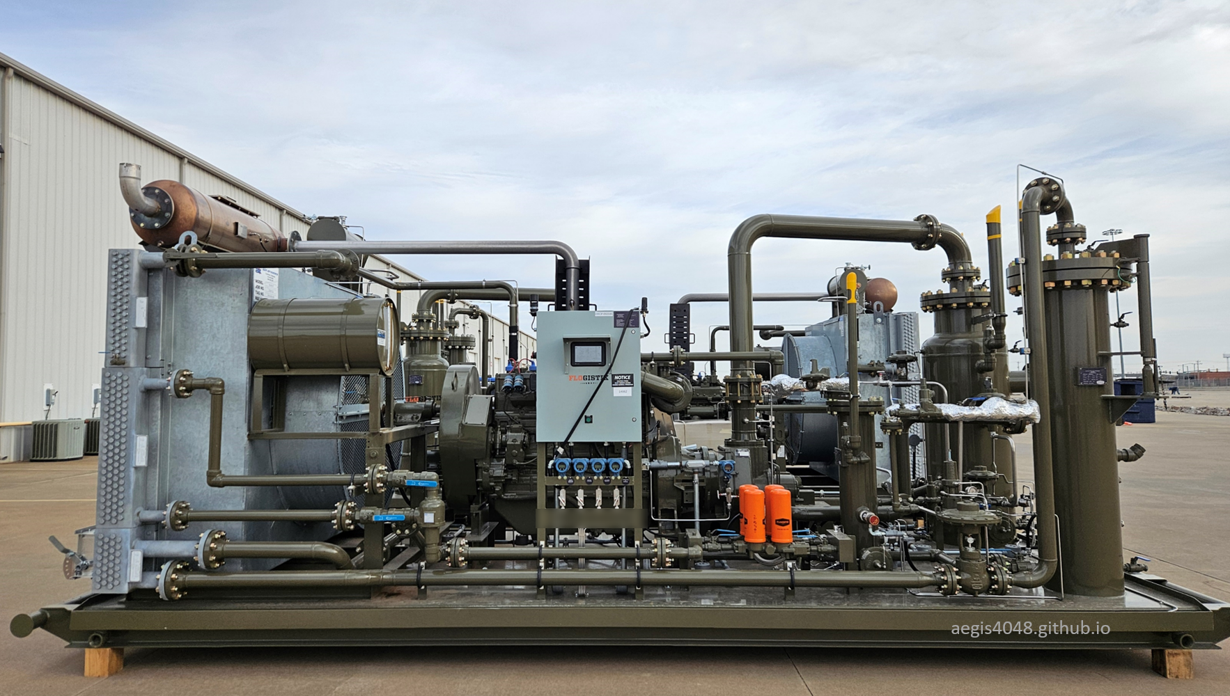
Figure 1: Flogistix FX17 gas-engine oil-flooded screw compressor.

Contents
- 0. Introduction
- 1. Characteristics of oil-flooded screw compressors
- 1.1. Single-stage, high compression ratio
- 1.2. Ideal for upstream wellsites
- 1.3. Lubricating (cooling) oil
- 1.4. Flowrate capacity and horsepower factors
- 1.5. Operating ranges
- 1.6. Shared cooling fan
- 1.7. 100% Turndown capability
- 2. Screw compressor (core) working principles
- 2.1. Rotors (male and female)
- 2.2. Direct-driven (non-geared)
- 2.3. Gear-driven (geared)
- 2.4. Gear Ratio & Limitations
- 2.5. Driver and Driving Shaft
- 3. Choice of a Driver: Electric Motor or Gas Engine
- 4. Compressor Package Key Equipment Summary
- 5. Process flow, model types and P&ID
- Type A. Full electric
- Type B. Electric w/ pneumatic dump
- Type C. Electric w/ pneumatic dump & recycle
- Type D. Gas engine
- 6. Pneumatic liquid dump cycle (blowcase)
- 7. Control Devices Working Mechanisms
- 7.1. Electric flow control valve
- 7.2. Pneumatic flow control valve
- 7.3. Solenoid valve
- 7.4. 3-Way thermostatic valve
- 7.5. Liquid level switches
- 7.6. Electric liquid pump
- 7.7. Pressure safety valves
- 7.8. Transmitters
- 7.9. Suction control valve
- 7.10. Back pressure valve
- Note 2: Control valve emissions
- 8. Pressure control
- 9. Temperature control
- 10. Lube oil contamination problems
- 10.1. Frequent shutdown/autostart units
- 10.2. Oversized electric units
- 10.3. High discharge pressure
- 10.4. High BTU
- 10.5. High inlet temperature
- 11. Concluding Remarks
1. Characteristics of oil-flooded screw compressors
The lubricating oil in screw compressors serves three critical functions. First, it seals the gap between the male and female rotors (see Section 2.1), which do not make direct contact. This sealing is essential for proper compression. Second, it lubricates the moving parts, reducing friction and wear. Third, it absorbs and dissipates heat from the compression process. Cooled oil enters the compression chamber, comes in direct contact with the hot compressed gas, absorbs heat, exits the chamber, passes through a cooling fan, and recirculates to continue the cycle.
Lubricating oil is typically one of the highest operating costs. If the compressor runs below the gas dew point, gas condenses and contaminates the oil. This lowers viscosity, promotes foaming, reduces lubrication quality, and degrades the performance of the coalescer in the discharge scrubber. The coalescer in the discharge scrubber requires cetain viscosity to capture oil effectively—its performance drops when the oil is thinned, resulting in lube oil carryover into salesline.
The primary concern is bearing damage caused by poor lubrication, due to both foaming (note that the lube oils come with additives that supress foaming) and reduced viscosity. Oil loss to the sales line is a secondary consequence. However, if the compressor consistently operates above the dew point and coalescer filters are regularly replaced, oil life can extend for years.
Applications prone to lube oil contamination include: [1] oversized electric units operating frequently in recycle mode, [2] units with frequent shutdowns and autostarts, [3] high discharge pressure systems, [4] high-BTU gas applications, and [5] systems with high inlet temperatures. For more details, see Section 10.
Compressor flowrate capacity and horsepower (HP) consumption are primarily influenced by (1) suction pressure, (2) discharge pressure, and (3) timing gear ratio. Of these, discharge pressure is typically outside operator control, as it is dictated by sales line pressure. Higher discharge pressure increases HP demand. Suction pressure, on the other hand, directly affects flowrate capacity—raising suction pressure increases flow, but also raises power consumption.
In most applications, suction pressure can be adjusted via the compressor’s PLC by setting a higher suction pressure setpoint. Note that suction pressure is essentially equal to vessel operating pressure (mimus friction loss). Maintaining a suction pressure means maintaining a source vessel's operating pressure. A properly sized compressor can maintain this target pressure on the inlet side by dynamically adjusting driver RPM (see Section 8.1 and Section 8.2 for more details). This approach is feasible for wellhead applications or vessels such as heater treaters, low-pressure separators, or vapor recovery towers (VRTs), although VRT suction pressure is only slightly adjustable (typically 1–5 psig). (See Section 8.4 for example setpoint scenarios.)
However, for atmospheric tanks—which cannot tolerate any pressure buildup—suction pressure cannot be artificially increased to boost flowrate. In such cases, the only way to increase flowrate capacity, without upgrading to a bigger unit, is by changing the gear ratio through timing gear replacement (refer to Section 2.3 for gear driven units). Gear changes are also useful when increasing the operating pressure of the source vessel is undesirable (higher operating pressure on an upstream vessel causes more flash volume to come from a downstream vessel, which are typically tanks or VRTs), or when suction pressure is already near the mechanical limit of the compressor (typically 50 psig) and cannot be raised further. In both scenarios, a higher gear ratio can increase flowrate capacity without altering suction pressure.
Increasing the gear ratio raises flowrate capacity, but it also increases horsepower consumption. However, gear ratio is also constrained by a maximum rotor tip speed specified by the compressor manufacturer (see Section 2.4), beyond which mechanical failure may occur. If the gear ratio is too high, the compressor may exceed its HP capacity, triggering a high-HP shutdown. Similarly, increasing suction pressure to push more volume may also cause an HP overload. Table 1 summarizes how suction pressure, discharge pressure, and gear ratio interact to affect flowrate and HP demand.
Every compressor has a defined horsepower limit, and staying within it is critical for reliable operation. Table 2 illustrates a scenario (highlighted in red) where a compressor runs out of horsepower due to the combined effect of high suction and discharge pressures. In such cases, the only solution is to upgrade to a larger unit with higher HP capacity.
It's important to note that there is no direct correlation between flowrate and horsepower consumption. For example, if a compressor's maximum flowrate capacity is 500 MCFD, increasing the flowrate from 100 MCFD to 300 MCFD will not affect HP consumption as long as it operates within the designed capacity.
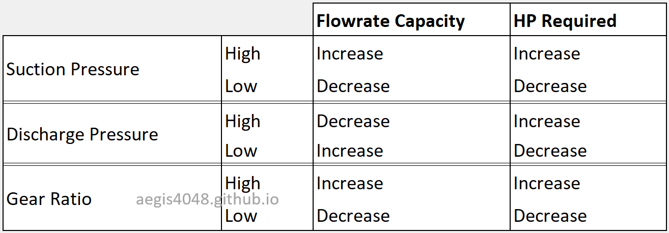
Table 1: A table summarizing the impact of increasing or decreasing suction, discharge, and gear ratios on compressor flowrate capacity and HP consumption.
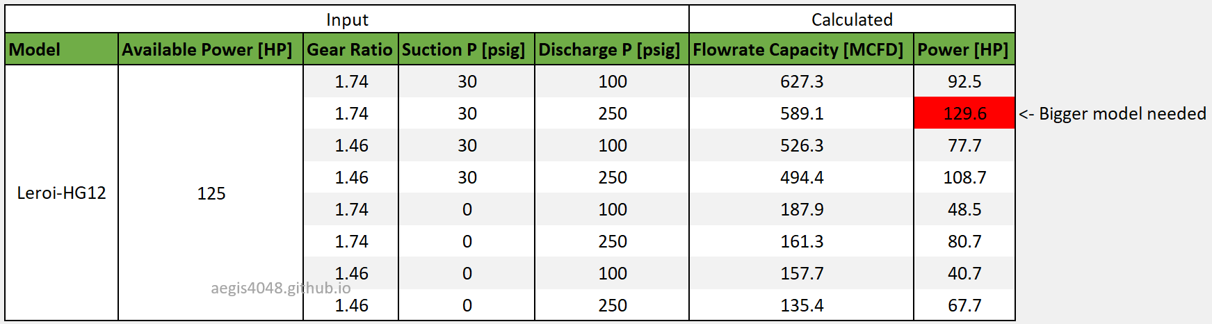
Table 2: Compressor sizing calculation using the Leroi HG12 series compressor model and Flogistix internal sizing software. The model has a maximum of 125 HP (as of Jan 2025). The table is sorted by the highest flowrate capacity. Compare the changes in numbers with varying gear, suction, and discharge conditions with Table 1 for a better understanding of their relationships. Note that the scenario highlighted in red exceeds the 125 HP limit, requiring a larger compressor. A potential solution is upgrading to the next bigger model, the Leroi HG17 series, which offers higher available HP.
This section outlines the general operating ranges of a screw compressor. These ranges are not definitive and can vary based on parts/models, applications, and operating conditions. Treat this as a general guideline rather than absolute.
Discharge pressure
:
60–350 psig. The upper limit of 350 psig is constrained by machine capability, while the lower limit of 60 psig is set by the minimum lube oil injection pressure required. For example, a Leroi compressor manual specifies that lube oil injection pressure must be at least 60–100 psig greater than the suction pressure.
Suction pressure
:
-14.7–50 psig. This range is set by machine capability. Exceeding 50 psig can cause machine downtime due to insufficient horsepower. Capable of pulling down to vacuum.
Temperature
:
120–230°F. Compressors are typically operated slightly below their maximum allowable temperature of 250°F—most commonly in the 200–230°F range. The standard 230°F operating temperature is governed by the mechanical setpoint of the 3-way thermostatic valve installed on the lube oil line (see Section 7.4). In gas engine models, this thermostat valve serves as the primary temperature control mechanism, since there is no dedicated driver for the cooling fan (see Section 9.2). Electric models, on the other hand, are equipped with a dedicated fan motor driver and can actively maintain operating temperature by adjusting fan RPM (see Section 9.1). For electric units, the thermostat valve "typically" acts as a secondary backup to contain sudden temperature spikes. Operating an oil-flooded compressor at low temperatures is not desirable, as it increases the risk of lube oil contamination from condensate formation during compression. Refer to Section 10 for more on this issue. A healthy temperature trend should resemble the profile shown in Figure 63.
Flowrate capacity
:
20–2,000 MSCFD. A compressor requires a minimum gas volume to avoid frequent activation of recycle mode (see Section 8.3). Extended periods in recycle mode are undesirable due to wasted energy. For electric models, low compression volumes may not generate enough heat of compression to maintain proper operating temperatures (see here). In Figure 64, recycle mode was active 65% of the time over a 16-day span, preventing the unit from reaching its 215°F temperature setpoint. This increases the risk of lube oil contamination under certain conditions. For gas engine models, running in recycle mode during hot summer days may lead to high-temperature shutdowns (see here). On the other end of the spectrum, the maximum flowrate limit can be extended by installing additional compressors.
Gear Ratio
:
1–3. While a higher gear ratio increases flowrate capacity, it also consumes more power. The gear ratio cannot exceed the machine's horsepower limit. Table 1 and Table 2 shows impact of gear ratio on flowrate capacity and HP demand. See Section 2.3 for working principles of timing gear ratios.
Horsepower Capacity
:
50–300 HP. This range varies significantly depending on the manufacturer/model.
Oil-flooded screw compressors share a single cooling fan for both the compressed gas and the lube oil—a feature not found in other compressor types like reciprocating or rotary vane models. Figure 59 shows the cooling fan on an electric model, and Figure 60 shows one on a gas engine model. The engine-driven unit includes an additional section dedicated to engine coolant.
The cooling fan’s operation differs between gas engine and electric models and should be understood accordingly.
For gas engine models, the compressor and fan share a single engine driver. RPM control is prioritized for the compressor, meaning the fan RPM follows the compressor speed. When the compressor runs at maximum speed, the fan does too; when the compressor slows down (e.g., during recycle mode), the fan slows as well. As a result, the fan alone cannot maintain a desired temperature on lube oil.
This is where the 3-way thermostatic valve (Section 7.4) becomes essential. It uses a thermal element that expands or contracts to adjust the mixing ratio of hot and cooled oil, regulating temperature in real time by determining how much lube oil flows through or bypasses the fan-cooled section.
However, this system becomes less effective when the fan cannot handle peak heat load—especially during hot summer conditions while in recycle mode. During recycle, compressor RPM drops to a minimum sustainable level, and so does the fan RPM. The reduced fan speed limits its cooling capacity, making it harder to maintain the desired oil temperature. Proper fan sizing is critical for engine models.
Electric models provide superior temperature control since they use a dedicated motor driver for the fan. This allows the fan RPM to be independently adjusted, regardless of compressor speed. The fan motor receives real-time lube oil temperature feedback from a transmitter and adjusts speed accordingly through the PLC to maintain the setpoint. In this setup, the thermostat valve serves as a secondary safeguard, helping to contain sudden temperature spikes if the fan cannot respond quickly enough (see below).
The electric models are capable of targeting both the lube oil temperature and the aftercooled gas temperature leaving the skid (see below). This is possible due to electric having dual real-time temperature control devices: thermostat valve and fan motor. However, this setup is uncommon because lube oil temperature is far more critical than aftercooled gas temperature.
See Section 9 for more details on temperature control.
Oil-flooded screw compressors achieve 100% turndown capability through recycle mode (Section 8.3). Turndown refers to the percentage reduction possible below a compressor's maximum design flowrate without causing shutdown. At 100% turndown, the compressor continuously operates from its maximum rated capacity down to essentially zero net flow by redirecting discharge gas back to suction via a recycle loop. The high pressure discharge gas first passes through a pressure reducing regulator (such as PR-1000, shown in Figure 15) to prevent high suction pressure shutdown (50 psig max), and then through a recycle valve (such as CV-1000, also shown in Figure 15) back into the suction line.
Continuous operation at 100% turndown prevents frequent start-stop cycles, reduces mechanical and thermal stresses, and maintains internal temperatures above the gas dew point. This helps avoid gas condensation into liquid, thereby preserving lube oil quality. Maintaining rotor rotation at minimal throughput also ensures immediate compressor responsiveness by eliminating the ramp-up delays associated with restarting the driver from zero RPM.
However, prolonged recycle operation carries an energy penalty. The compressor repeatedly recompresses the same gas, consuming energy (electricity or fuel gas) without delivering net throughput. In electric models, prolonged recycle may not generate sufficient heat to maintain temperatures above the gas dew point, increasing the risk of lube oil contamination (see below). In engine models, extended periods in recycle mode can cause high-temperature shutdowns, particularly during hot weather, due to reduced fan RPM limiting cooling capability (see below).
2. Screw compressor (core) working principles
BEFORE YOU READ: The term "compressor" can refer to two things: a complete compressor package, which includes suction/discharge scrubbers, fans, valves, piping, and the "core" compressor, or the "core" compressor itself. The "core" compressor is the part of the package where actual compression occurs, consisting of two helical rotors inside a compression chamber. This section focuses exclusively on the "core" compressor.
The core of an oil-flooded screw compressor consists of two helical rotors—a male and a female rotor—enclosed within a compression chamber. The rotors are driven by a shaft, which transfers torque from a driver (either a gas engine or an electric motor) to the rotors. A screw compressor can be either direct-driven (non-geared) or gear-driven. In a direct-driven configuration, the driving shaft is directly connected to the rotor. In a gear-driven configuration, the driving shaft is connected to timing gears, and the shaft linking the gear to the rotor turns the rotor through the gear. In most screw compressor applications, the driving shaft is connected to the male rotor, but in oil-flooded screw compressors used in the oil and gas industry, the shaft is typically connected to the female rotor or gear. The rotor/gear connected to the shaft (e.g., the female rotor) is the one doing the work, while the other rotor/gear (e.g., the male rotor) spins freely as it is driven by the intermeshing action of the female rotor/gear. As the rotors rotate, gas is drawn into the chamber through the suction port. The intermeshing rotors trap and progressively reduce the volume of the gas as it moves along the length of the rotors toward the discharge port. This reduction in volume increases the gas pressure. The chamber is "flooded" with lubricating oil, which serves multiple purposes: it seals the gaps between the rotors, lubricates the moving parts, and absorbs the heat generated during compression. The compressed gas, now mixed with oil, exits the chamber and is separated from the oil in a downstream discharge scrubber before being sent to the pipeline, while the lube oil is recirculated back into the system.
Figure 2: 3D animation of screw compressor working principle. Low pressure gas enters from the top (blue) and high pressure gas leaves from below (red). GIFs adapted from: video source.
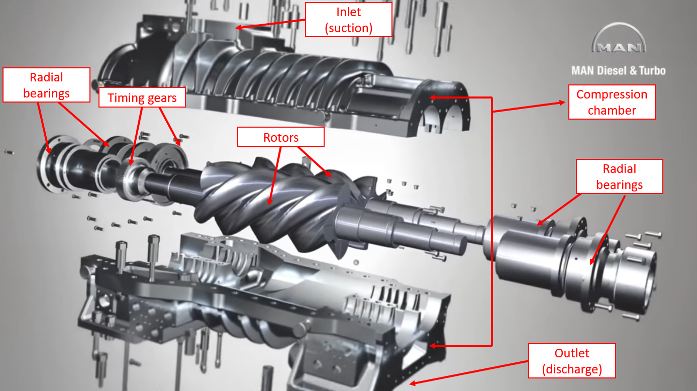
Figure 3: Screw compressor key parts labeled. Image adapted from: video source.
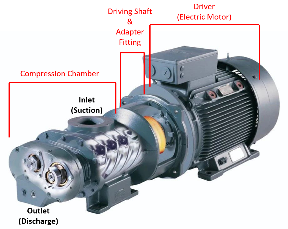
Figure 4: Compression chamber, shaft, and driver of a screw compressor. The driver (in this example, an electric motor) transfers its torque to the rotor through a driver shaft. The shaft turns either the male or female rotor, while the other rotor spins freely due to the intermeshing action of the driven rotor. Compression takes place inside the compression chamber.
2.1. Rotors (male and female)
A screw compressor features twin helical rotors: one with fewer lobes, called the male rotor, and one with more lobes, called the female rotor. In the upstream oil and gas industry, oil-flooded screw compressors typically use a 4:6 (male:female) female-driven design. For a non-geared, direct-female driven compressor, this means that for every 1,000 RPM of the female rotor, the male rotor will rotate at 1,500 RPM due to the lobe ratio. The driving rotor (female) receives rotational energy from the driver, while the driven rotor (male) is turned by the intermeshing action of the driving rotor. (Note that this RPM ratio and the driven rotor configuration do not apply to geared units. In geared units, the female "gear" drives the male "gear," and the male "rotor," connected to the male gear, turns the female rotor.)
Properly manufactured rotors in oil-flooded screw compressors should never experience metal-to-metal contact, as this minimizes wear and ensures longevity. The lubricating oil provides a sealing barrier between the rotors, preventing gas from escaping during compression and allowing the rotors to maintain indirect contact through an oil film. This is possible because liquids, such as oil, are incompressible.
Maintaining lube oil quality is essential to prevent damage to the rotor bearings. When oil is contaminated due to hydrocarbon condensates mixing with lube oil, the lube oil viscosity decreases, and foams appear. This foaming significantly reduces lubrication quality by introducing gas bubbles into the oil, impairing the oil's ability to create a protective lubricating film between critical components. Bearings, which rely on a stable oil film for protection, experience increased friction and accelerated wear due to inadequate lubrication. Additionally, foamed oil is easily carried over into the compressor’s discharge gas stream, contaminating downstream equipment and increasing operational costs. Operating above the dew point of the gas is critical to avoid lube oil quality degradation. For lube oil contamination details, see Section 10.
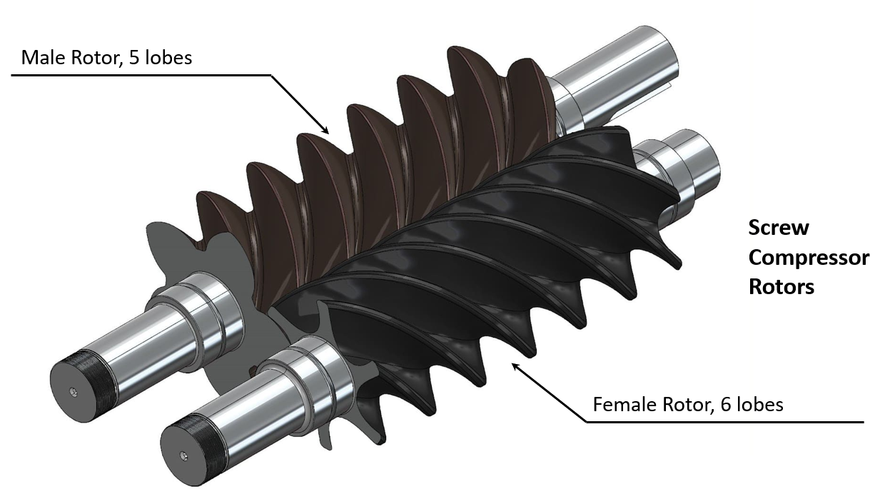
Figure 5: An illustration of the male-female helical rotors for screw compressors. This specific drawing has a 5:6 male-female lobe ratio.
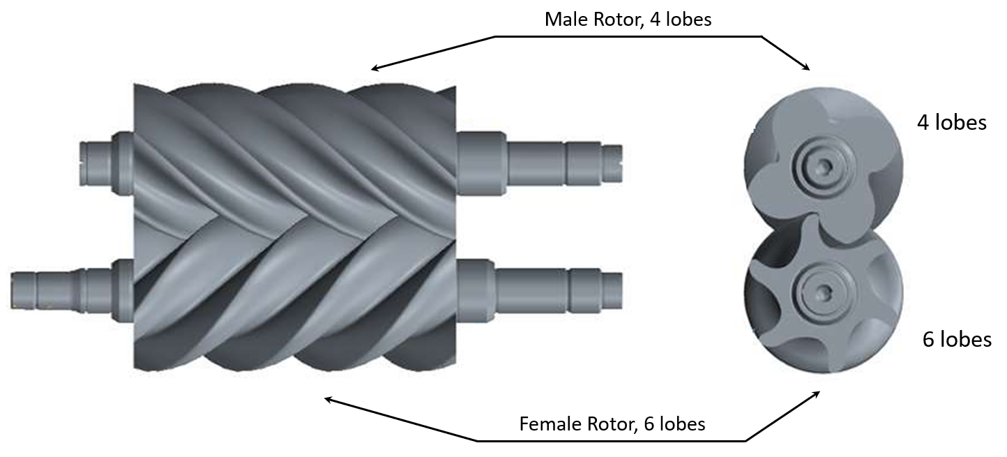
Figure 6: An illustration of the male-female helical rotors for screw compressors. This specific drawing has a 4:6 male-female lobe ratio. This design is used in the Leroi HG series, which is specifically designed for oil-flooded screw compressors in the oil and gas industry.
2.2. Direct-driven (non-geared)
For any screw compressor application, a driver (gas engine or electric motor) transfers its rotating energy to a driving shaft. In a direct-driven configuration, the shaft is directly connected to one of the rotors. The rotor directly connected to the driving shaft is called the driving rotor, while the other rotor is called the driven rotor, as it is driven by the rolling and intermeshing actions of the driving rotor.
Energy transfer order
- A driver (gas engine or electric motor) generates rotating energy.
- Rotating energy is transferred to a driving shaft.
- The driving shaft turns the driving rotor.
- The driven rotor is turned by the rolling and intermeshing actions of the driving rotor.
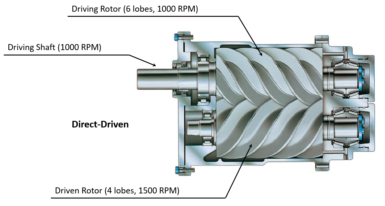
Figure 7: An illustration of a direct-driven rotary screw compressor. The driving shaft is connected to a driver (not shown). The driving shaft is directly connected to the driving rotor, turning it, while the driven rotor spins freely due to the intermeshing action of the driving rotor.
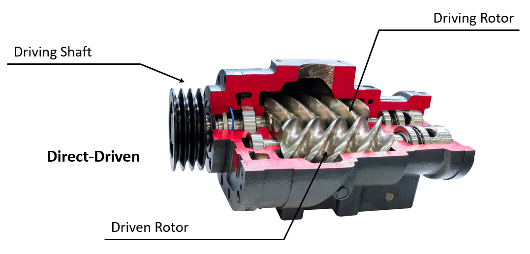
Figure 8: A real-world example of a direct-driven compressor, as illustrated in Figure 7.
2.3. Gear-driven (geared)
Some screw compressors come with internal timing gears. In a gear-driven configuration, the driving shaft is indirectly connected to the rotors through a pair of gears. The purpose of the gear pair is to adjust the RPM of the rotors without changing the male:female lobe ratio. Typically, a larger gear is directly connected to the driving shaft. The gear directly connected to the driving shaft is called the driving gear, while the other gear is called the driven gear.
In Figure 9 below, assume the driving gear has 30 teeth and the driven gear has 15 teeth, resulting in a gear ratio of 2:1. If the driving shaft operates at 1,000 RPM, the driving gear will also rotate at 1,000 RPM. Due to the 2:1 gear ratio, the driven gear will rotate at 2,000 RPM. The driving rotor, connected to the driven gear through the axial bearing, will also rotate at 2,000 RPM. Given a lobe ratio of 4:6 (driving rotor:driven rotor), the driven rotor will rotate at 1,333 RPM (since 2,000 RPM × 4/6 = 1,333 RPM). Despite the input shaft having only 1,000 RPM, the driving rotor achieves 2,000 RPM, and the driven rotor achieves 1,333 RPM, resulting in an overall speed increase. This speed increase provides higher flowrate capacity at the cost of higher horsepower consumption.
Energy transfer order
- A driver (gas engine or electric motor) generates rotating energy.
- Rotating energy is transferred to a driving shaft.
- The driving shaft turns the driving gear.
- Driving gear turns the driven gear.
- Driven gear is connected to the driving rotor through its axial bearings. Driven gear turns the driving rotor.
- The driven rotor is turned by the rolling and intermeshing actions of the driving rotor.
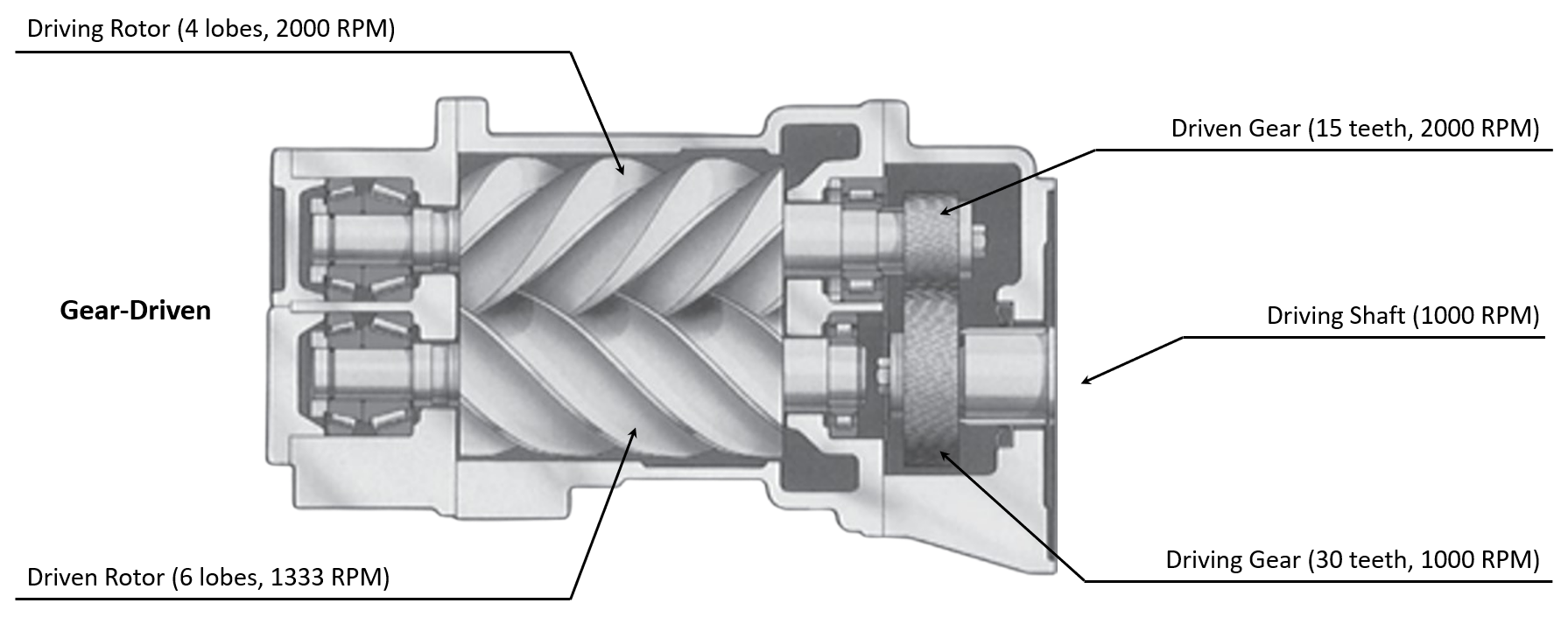
Figure 9: An illustration of a gear-driven rotary screw compressor. The driving shaft is connected to a driver (not shown). The Note that there's a gap beween the driving gear and the driven rotor, suggesting that the energy from the driving shaft is not directly transferred to the driven rotor.
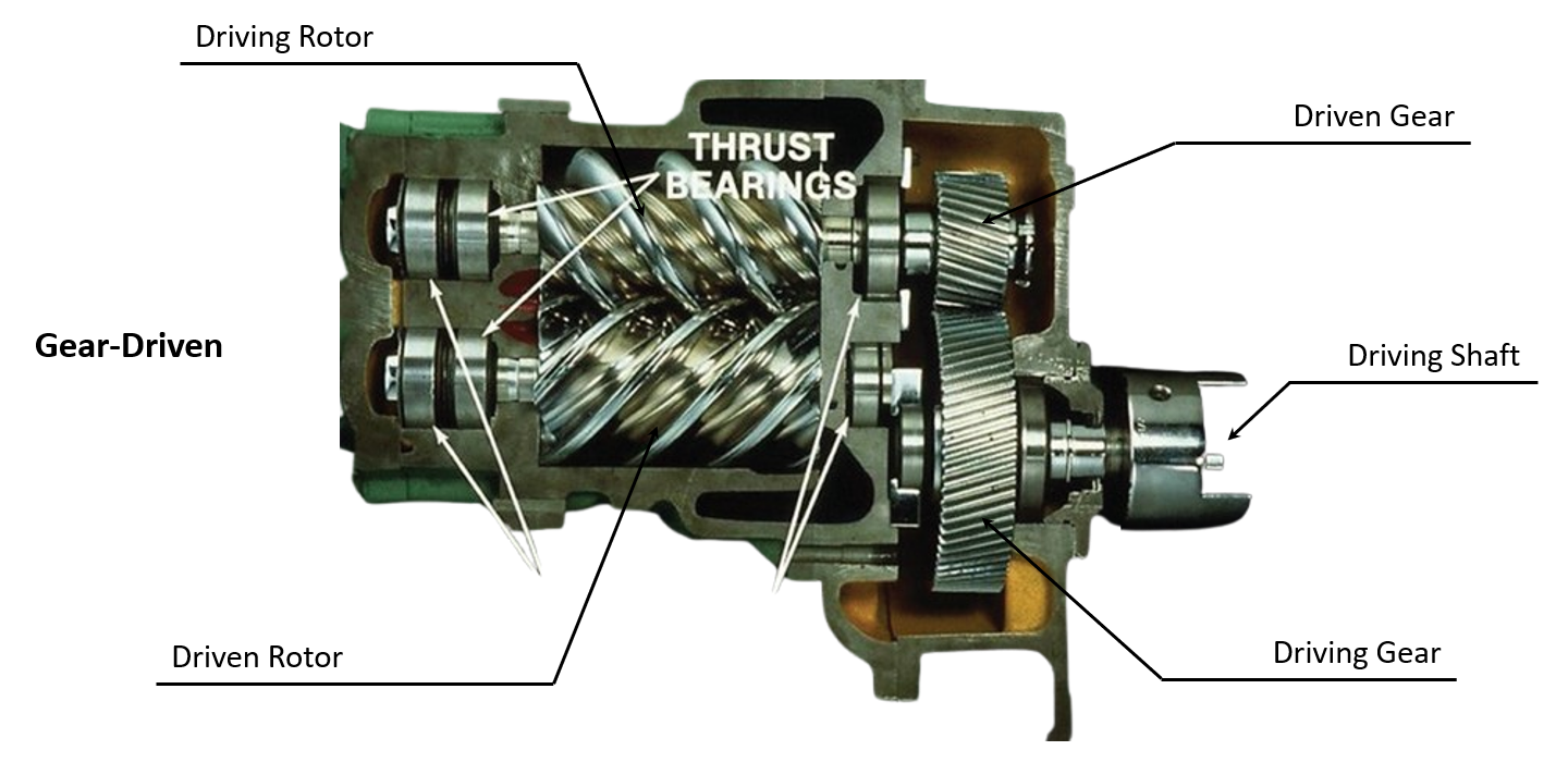
Figure 10: A real-world example of a gear-driven compressor, as illustrated in Figure 9.
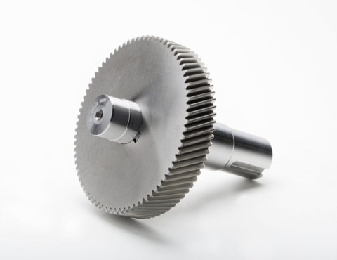
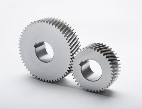
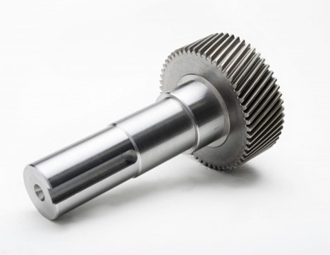
Figure 11: Illustration of gears.
2.4. Gear Ratio & Limitations
Increasing the gear ratio increases rotor RPM, allowing a compressor to process more gas volume. For example in Table 2, for Leroi-HG12 model with suction pressure at 30# and discharge pressure at 100#, increasing the gear ratio from 1.46 to 1.74 increased the flowrate capacity from 526 MCFD to 627 MCFD. However, does this mean you can use a massive gear ratio without limits? No. There are two fundamental limitations:
1. Increasing RPM increases horsepower consumption. All machines have their own maximum HP limits, and the RPM cannot exceed the machine's HP capacity.
2. The rotors have a maximum tip speed. Gear ratios should not cause the machine to exceed this limit. Typical screw compressor tip speed limits range between 30–50 m/s (the unit is in metric because rotor diameters use the metric system). For example, the Leroi HG12 series has a rotor diameter of 127.5 mm and a maximum rotor tip speed of 37 m/s. This specific model supports both geared and non-geared configurations. Assume a non-geared configuration with 2150 RPM on the driving shaft. The tip speed of the driving rotor is:
Now assume the a geared configuration with a 2.57 gear ratio. The tip speed of the driving rotor becomes:
The calculation shows that the gear ratio should not be increased beyond 2.57 due to the rotor tip speed nearing the mechanical limit of the machine, set at 37 m/s.
2.5. Driver and Driving Shaft
The driver is the energy source that generates rotating energy, and the driving shaft is the connecting bridge between the driver and the rotors/gears. A driver can be either a gas engine or an electric motor. The rotational energy from the driver is transferred to the screw rotors through a driving shaft. Figure 12-A and 12-B below show gas engine and electric motor driver connections to the compressor through a driving shaft.
Electric models have separate motor drivers for the compressor and fan (shown in Figure 61 and 62). In contrast, engine models use a single engine driver to power both the compressor and fan (shown in Figure 65 and 66). This creates temperature control more difficult for engine models compared to electrics. See Section 9 for temperature control mechanisms for both models.
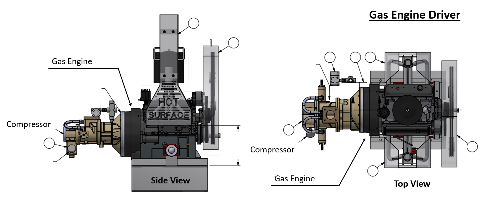
Figure 12-A: 3D illustration of a gas engine driver and a compressor. A driver shaft is located inside the adapter fitting between the engine and the compressor.
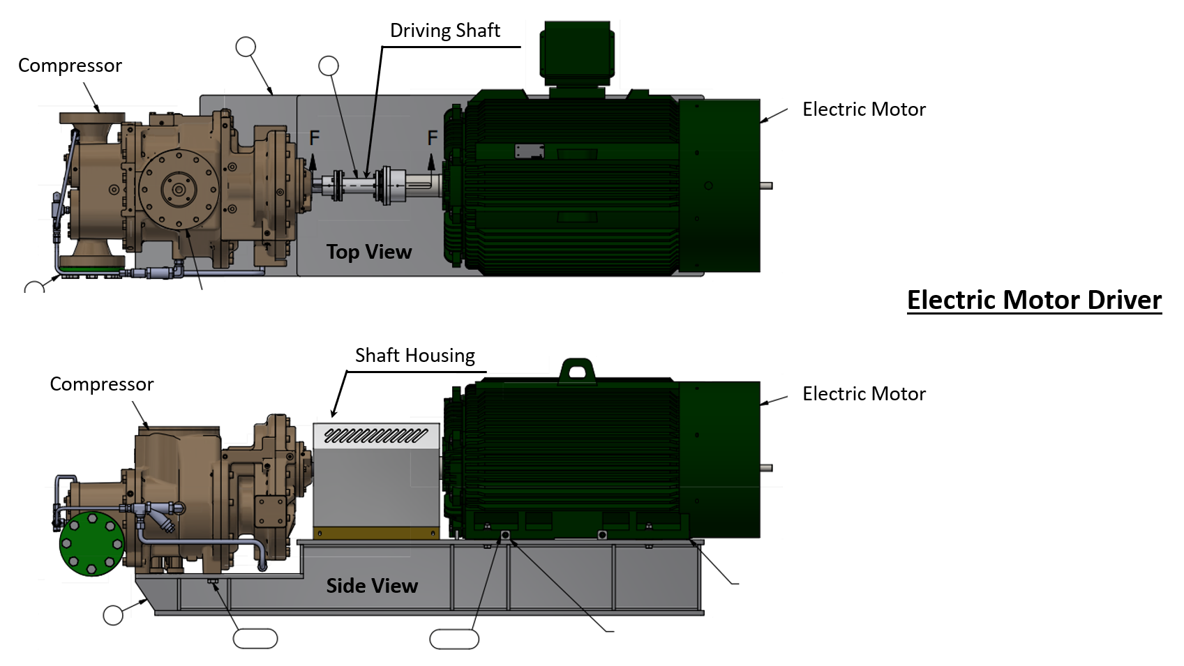
Figure 12-B: 3D illustration of an electric motor and a compressor. The compressor and the motor are connected through a driver shaft.
3. Choice of a Driver: Electric Motor or Gas Engine
In short, electric models are almost always superior—as long as the site has access to electric power. Electric units offer better driver RPM control, temperature regulation, quicker response to source pressure fluctuation, and less maintenance compared to engine-driven models. They also tend to leave a smaller carbon footprint—though this depends on the local power generation source.
-
Presence of electric power
Not all wellsites have access to grid power. Some are too remote, and extending electric lines or installing generators may be cost-prohibitive. In such cases, gas engine units are selected due to lack of alternatives.
-
Concerns over emissions
Gas engine models burn fuel directly at the site, producing on-site emissions. Electric units do not emit at the compressor, but instead draw electricity from the grid. If the electricity comes from coal-fired plant, indirect emissions may be higher than on-site combustion. If the source is natural gas or renewables, electric units are cleaner. Operators must assess the local power mix to compare total emissions accurately.
-
Driver RPM control
Electric units can ramp up driver RPM faster and more precise than engine units, allowing quicker response to changing inlet pressure conditions. Gas engines respond slower because, unlike electric units which use readily available electricity, they must first burn fuel gas to generate the energy needed to turn the engine driver. See Section 8.2 for detailed discussion on RPM control mechanisms for electric vs. engine models.
-
Maintenance
Engine units require more frequent maintenance than electric units due to having more moving parts. Compare Figure 13 (engine) with Figure 14 (electric)—it's clear that engine models involve significantly more components than their electric counterparts.
-
Temperature control
Electric units have two motor drivers for a compressor and a cooling fan (see Figure 61), allowing independent RPM control for each. The VFD on the cooling fan motor provides primary control on the cooling fan, and the 3-way thermostatic valve (see Section 7.4) on the lube oil line provides secondary backup cooling in case the fan RPM control couldn't contain a sudden rise in process temperature. This dual control system makes electric units superior in managing temperature.
Engine units have only one shared engine driver for both fan and the compressor (see Figure 65 and 66). Primary control is given to the compressor, meaning the cooling fan RPM floats. Without a dedicated fan motor, the 3-way thermostat valve becomes the only real-time temperature control mechanism. This setup becomes inadequate if the cooler can't handle the peak heat load. It's especially problematic during recycle mode, when compressor RPM drops—causing fan RPM to drop as well. While heat of compression is reduced, the heat from fuel gas combustion still remains significant. The post-catalyst temperature for the exhaust fuel gas operates between 250-1300F°. Lower fan speed reduces airflow, which degrades cooling performance. This could potentially trigger high temperature shutdown during hot summer conditions .
There's a lot going on to fully understand temperature control differences between electric vs. engine models. Read both Section 7.4 and Section 9 for full understanding.
3.1. Gas engine compressor
Figure 13 below is a picture of the Flogistix FX12 gas engine-driven oil-flooded screw compressor. This specific unit has two cooling fans (both powered by the gas engine): one for the discharge gas and lubricating oil, and another for the engine coolant. Larger units, such as Flogistix FX17 (Figure 1) or FX20, share a single fan for cooling the discharge gas, lubricating oil, and engine coolant. This design varies depending on the model.
The burned exhaust gas is vented through the top vent line, serving as an emissions source that many companies aim to eliminate by switching to electric models. The small pot mounted on top of the lube oil cooler contains a catalyst that triggers chemical reactions to convert harmful VOCs into less harmful compounds—for example, hydrocarbons and carbon monoxide into CO₂, and NOₓ into nitrogen and oxygen. The pot has a silencer that reduces reaction noises.
The engine coolant circulates between the engine and fan to keep engine temperature within safe limits. The unit also includes an engine oil reservoir and an oil level maintainer. If the oil level gets too low, the maintainer triggers an electric switch that sends a shutdown signal to the PLC.
Although not visible in the photo, the unit has a solar panel as a backup power source for the PLC. While the engine's alternator is the primary source of DC voltage (similar to a car), it may not run long enough between autostart/stop cycles to fully recharge the battery. The solar panel helps maintain battery voltage for reliable PLC operation in such cases. Engine starting requires significant power, which can vary based on engine size, compressor load, starting conditions, and fuel quality—factors that all contribute to starting difficulty.
Overall, gas engine units require larger cooling capacity due to the additional heat generated from fuel gas combustion—a factor that doesn't apply to electric models. Pre-catalyst exhaust gas temperatures typically range from 400–600°F, while post-catalyst temperatures can reach up to 1300°F.
The engine unit has one shared driver for both the cooling fans and the compressor. The driver prioritizes compressor RPM, meaning the cooler RPM floats. This makes temperature control difficult. See Section 9.2 for engine model temperature control mechanisms.
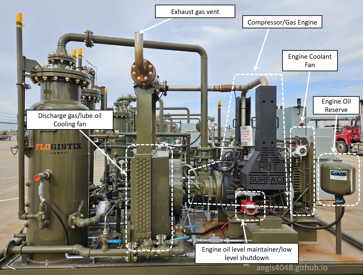
Figure 13: Flogistix FX12 gas engine-driven oil-flooded screw compressor.
3.2. Electric motor compressor
Figure 14 below is a picture of the Flogistix FX12 electric motor-driven oil-flooded screw compressor. This model has one fan for cooling the discharge gas and lubricating oil. It includes two motors: one for the cooling fan and one for the compressor. Its design is much simpler than the gas engine model, as it eliminates the need for engine coolant, engine oil, exhaust piping, a low engine oil level shutdown switch, a solar panel, and other components. The design and maintenance are simpler than gas engine models simply because fewer parts are involved. However, electric models are not viable in the absence of an electricity source.
The electric unit has two motor drivers for the compresesor and the cooling fan. This features competitive temperture control advantages compared to engine units that have only one shared engine driver for both. For electric model temperature control details, see Section 9.1.
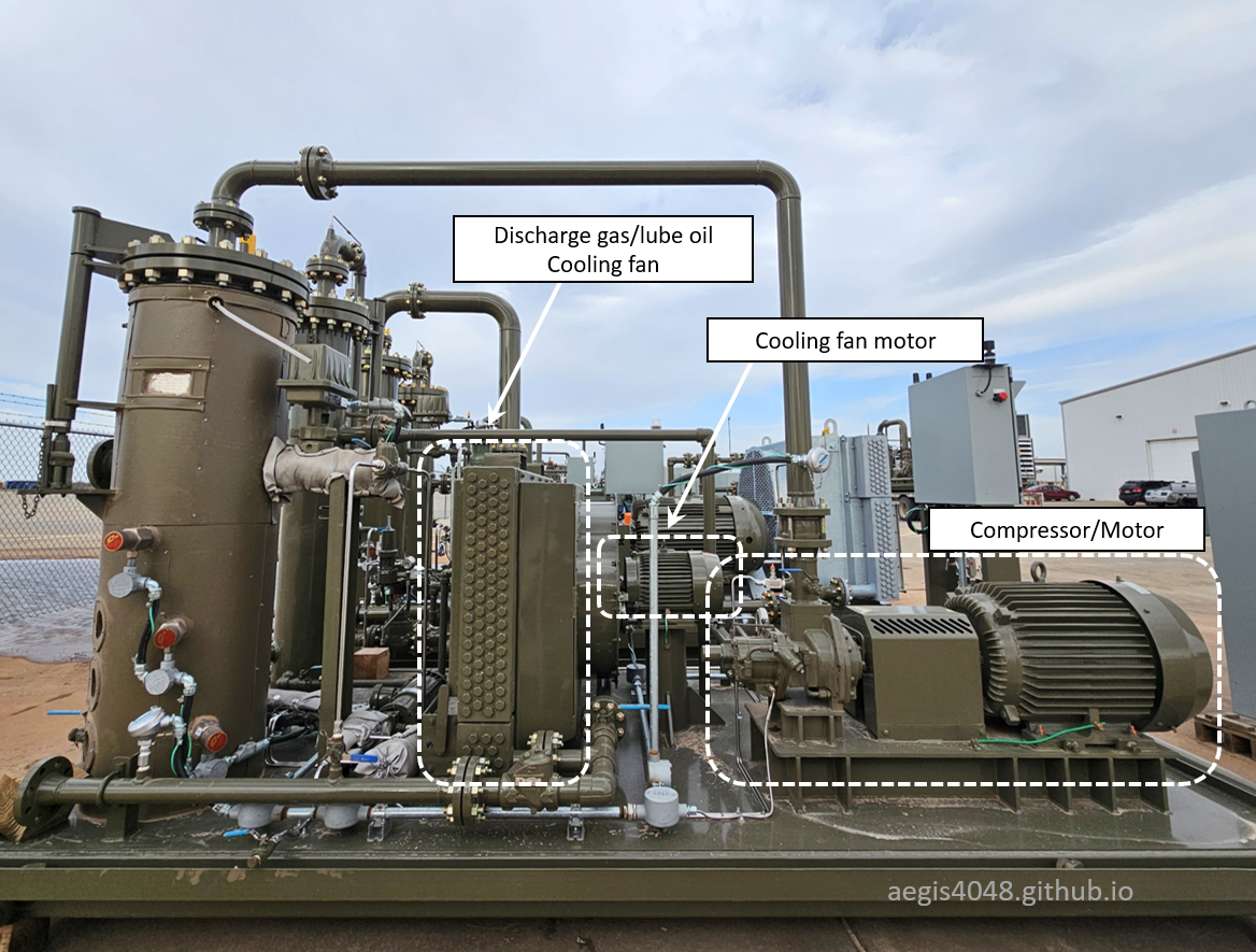
Figure 14: Flogistix FX12 electric motor-driven oil-flooded screw compressor.
4. Compressor Package Key Equipment Summary
BEFORE YOU READ: I recommend switching back and forth with Figure 15, 16, 17, and 18 while reading this section to aid your understanding.
A compressor "package" refers to a complete system of process equipment that handles a compression process. Below is a quick overview of each key equipment before explaining the P&ID and process flow.
Suction Scrubber
:
A small two-phase separator that removes entrained liquids. Liquids fall due to gravity, while gas flows upward. Residual liquid is captured by a mist extractor/coalescer. Accumulated liquid is periodically removed by a discharge system. The vessel has level switch controller (LS-1010) and liquid dump valve (CV-1011) for automatic dump. It also has high liquid level shutdown (LSHH-1000). The right-side bottle in Figure 36 is the suction scrubber.
Suction Liquid Discharge System
:
A liquid discharge system is required because the suction scrubber does not have enough pressure to push liquids out on its own. Liquids from compressor scrubbers are always dumped to atmospheric tanks, which typically have inlet ports located at the top—15 to 25 feet above ground level. This elevation requires at least 6.5 to 10.8 psi of pressure to overcome the hydrostatic head (0.433 psi/ft). To achieve this, the system may use either a pressurized blowdown via an integrated blowcase or an electric pump.
Integrated Blowcase
:
The blowcase is integrated inside and at the bottom of the suction scrubber. In Figure 16, V-100 is the suction scrubber, and V-101 is the blowcase. Liquid knockouts fall to the bottom of the scrubber and on top of the blowcase. Liquid flows downward into the blowcase due to gravity and accumulates inside. A level switch (LS-1010) detects the liquid level inside the blowcase and activates a dump cycle when the level rises sufficiently. Pressurized gas from the discharge scrubber (V-300) goes through a pressure reducing regulator (PR-1000) to provide sufficent pressure while not triggering high suction pressure shutdown, and enters the blowcase to "blow away" the accumulated liquids. Pressure equalizing valve (CV-1001), pressure charge valve (CV-1010) (see Note 1), liquid dump valve (CV-1011), and liquid level switch (LS-1010) (see Section 7.5) make up the whole automated blowcase liquid dump system. The blowcase is not present in models that use an electric liquid pump for the dump cycle. Refer to Section 6 for detailed blowcase working mechanism.
Electric Liquid Pump
:
Used when a pneumatic liquid dump with a blowcase configuration is undesirable. In Figure 15, P-100 is the pump, and M-100 is its electric motor. The pump activates via an electrical signal from LSH-1000 when the liquid level is high and turns off once the level reaches the LSL-1000 setpoint. See Figure 34.
Compression Chamber
:
Where compression occurs. It has two inlets (gas and lube oil) and one outlet (pressurized gas-oil mixture). Intermeshing helical rotors reduce gas volume, increase pressure, and generate heat. Heat is absorbed by the lube oil flooding the chamber. The compressor is controlled by the PLC and powered by a driver. Refer to Section 2 for compressor details.
Driver
:
Either a gas engine or electric motor. Generates rotational energy to turn the compressor rotors via a shaft. Separate or shared drivers can also power cooling fans. Figure 15, 16, and 17 show eletric compressors. Figure 18 shows a gas engine compressor.
Electric models use two motor drivers—one for the compressor, one for the fan—with independent RPM control for each. Gas engine models use a single engine crankshaft driver to drive both, prioritizing compressor RPM while the fan RPM floats. This makes temperature control more challenging in gas engine models. See Section 9 for more details.
Discharge Scrubber
:
A small two-phase separator that separates pressurized and mixed-phase lube oil and gas. The vessel also acts as a reservoir for lube oil. Gas flows upward, while lube oil falls due to gravity. Around 97% of the lube oil is separated, but 3% remains as mist, requiring a coalescer to minimize oil loss. While the coalescer captures most of the entrained oil, a tiny fraction is lost to the gas line over time, necessitating periodic oil refills. Unlike the suction scrubber, the discharge scrubber doesn't require an independent liquid discharge system due to its high pressure. The vessel is equipped with a low-level shutdown for lube oil loss. The left-side bottle in Figure 36 is the discharge scrubber.
Fuel Pot Scrubber
:
Used for gas-engine model only. In Figure 18, V-600 is the fuel pot scrubber. Combustion engine demands clean, dry fuel gas, achieved through the fuel pot scrubber which removes any residual entrained liquids one more time after the discharge scrubber (V-300). Unlike the suction scrubber V-100, V-600 doesn't need a blowcase dump system - its position downstream of the compressor provides sufficient pressure for liquid removal, though it still requires a level switch (LS-6000) and dump valve (CV-6000) for automation.
Back Pressure Valve
:
A back pressure valve (BPV) is installed on the outlet line of the discharge scrubber. It maintains a set pressure on the vessel, ensuring proper lube oil injection pressure. The Leroi HG series manual specifies oil injection pressure to be 60–100 psi higher than the suction pressure. See Section 7.10 for more details.
Cooling Fan
:
Provides cooling for engine coolant (gas engine model only), lube oil, and compressed gas. The fan has independent sections for different process fluids. Figure 59 shows a fan for electric model, and Figure 60 shows a fan for gas engine model. Lube oil and gas share one fan, while engine coolant may share the same fan or have an independent one depending on model design. The fan is either electric motor driven, or gas engine drive.
3-Way Thermostatic Valve
:
Adjusts the mixing ratio of hot oil (bypass cooler) and cooled oil to achieve a target temperature. For engine models, this valve serves as the only real-time control device. For electric models, the valve acts control, while the fan motor provides primary control. See Section 7.4 for more details.
Recycle Valve
:
When open, directs pressurized gas back to the suction scrubber. Because the suction side operates at a much lower pressure than the discharge side, gas preferentially flows back to the suction side. The valve receives open/close signals from the PLC. Recycle mode activates when the gas source vessel (tanks, VRTs, heaters, separators) lacks sufficient gas volume. Overdrawing the source vessel can lead to pressure control failure or vessel collapse. Recycle mode is preferred over a hard shutdown for operational continuity. The valve may be electric or pneumatic. The pneumatic types require solenoid valve (see Section 7.3) installed on the supply pressure line receive electric signals from the PLC. Details on recycle mode operation is covered in Section 8.3.
Skid
:
A metal base on which compressor package components are mounted. The skid allows the compressor package to be transported by trucks or trailers.
5. Process flow, model types and P&ID
This section explains the general process flow and piping and instrumentation diagrams (P&ID) for oil-flooded screw compressor operations. The P&IDs are simplified for illustration purposes and do not include all components. This section covers the four most common oil-flooded screw compressor design scenarios, listed from the simplest to the most complex designs (not in order of customer demand). For efficient learning, I recommend reading them in order. Zoom in or click on the diagrams in Figure 15, 16, 17, and 18 for magnified view. Refer Table 3 for P&ID component labels.
Process Flow Order
- Gas enters the suction scrubber; entrained liquids fall to the bottom and are periodically removed via pressurized gas blowdown or liquid pump.
- In the suction scrubber, gas travels upward, with residual liquid mist captured by a mist extractor.
- Gas and lube oil enter the compression chamber, where both are mixed and pressurized. When the oil enters the chamber, its temperature is fixed at around 230°F, controlled by the thermostatic valve setpoint.
- Heat is generated during compression. Lube oil absorbs it, causing the temperature to rise by 3–6°F higher than 230°F.
- The pressurized two-phase mixture exits the chamber.
- The two-phase mixture enters the discharge scrubber.
- In the discharge scrubber, 97% of the lube oil separates and falls to the bottom, while 3% is captured by a coalescer. A tiny fraction is still lost to the pipeline, requiring periodic lube oil refills.
- Gas is cooled by a fan to meet pipeline temperature requirements before leaving the skid.
- Separated lube oil undergoes a cooling process. Depending on its temperature, some oil bypasses the cooling fan, while some enters the fan to be cooled. The hot bypass oil (B port) and cooled oil (C port) mix at the 3-way thermostatic valve. The valve adjusts the mixing ratio to maintain the lube oil setpoint temperature around 230°F. The mixed oil exits the valve through the A port.
- Lube oil passes through the oil filter and re-enters the compression chamber to repeat the cycle.
- If the PLC activates recycle mode, the recycle valve opens, and gas is circulated within the skid instead of being discharged out of the skid.
P&ID Component Labels
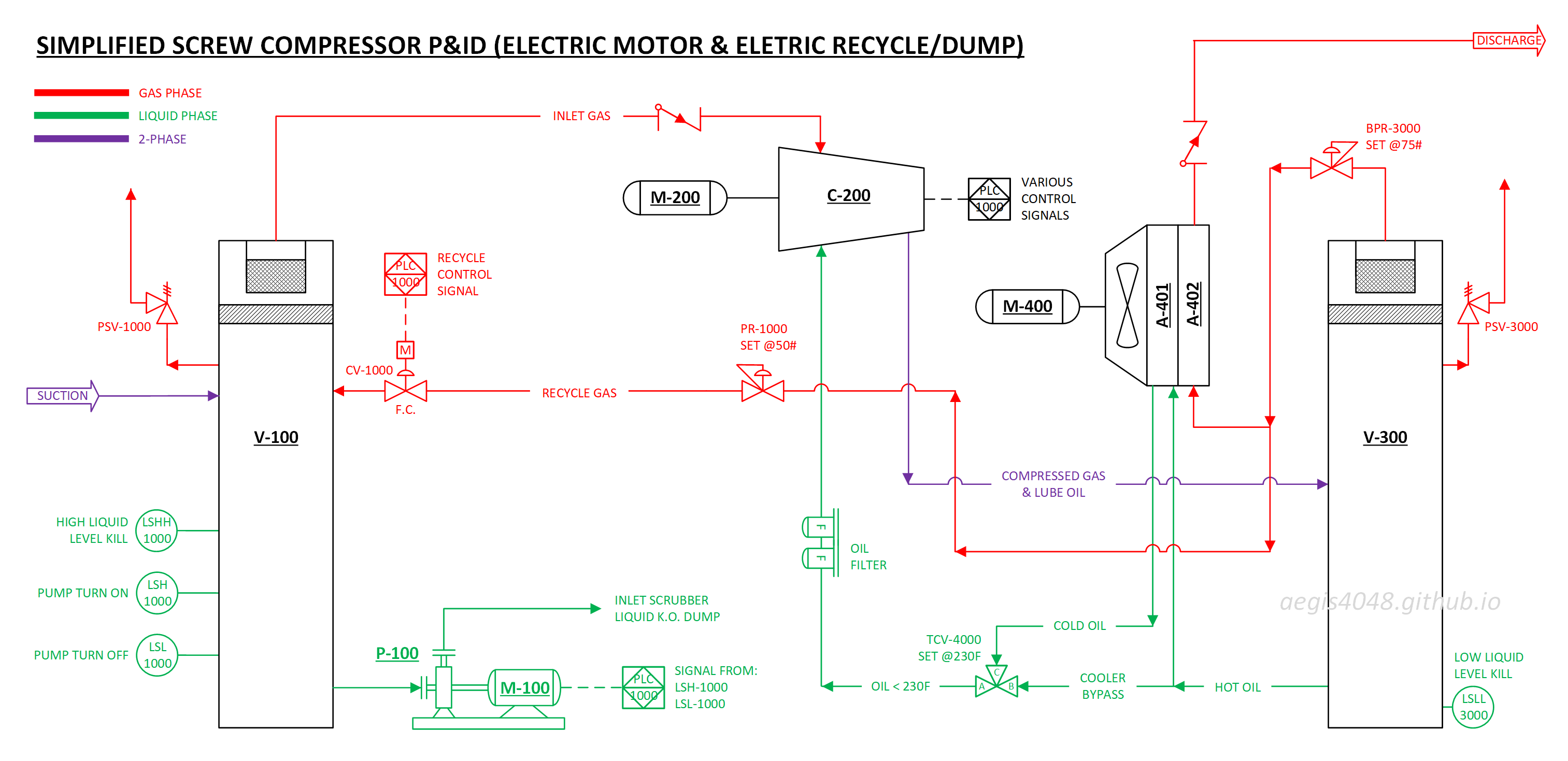
Type A: Electric Driver/Electric Pump Dump/Electric Recycle
This is the least popular model due to higher cost. This configuration is fully electric, with the compressor driver, recycle valve, and liquid dump system all powered electrically. It is the simplest design among the four but also the least common. This is because running an electric liquid pump increases operation and maintenance costs compared to a pneumatic liquid dump system. This configuration is typically used when:
- The customer prefers an electric model over a gas engine to minimize carbon footprint.
- They don't have clean instrument air supply to (instead of natural gas) to operate pneumatic valves.
- It is not easy or feasible to route control valve vent gas to a clean disposal system (most flow control valves vent used pilot gas, see Note 2)
All conditions must be satisfied for this configuration to be chosen. While most operators do not prioritize control valve vent gas due to minimal emissions, some companies maintain a zero-tolerance stance on emissions, making this design necessary.
Because the system uses an electric motor-driven liquid pump for liquid discharge, it does not require complex control valves or pneumatic pilot gas lines to operate a liquid dump system. It also eliminates the need for an integrated blowcase inside the suction scrubber. Instead, the system uses two additional liquid level switches (positioned below the high liquid level kill switch) to control the pump. In Figure 15 below, when the liquid level rises above LSH-1000, the switch sends a signal to turn on the pump. The pump operates until the liquid level drops to LSL-1000, at which point it turns off.
However, this configuration has some downsides. The electric actuator for the recycle valve requires significantly higher maintenance costs and more frequent maintenance compared to a pneumatically operated recycle valve. Additionally, the operational and maintenance costs of the electric pump are higher than those of a pneumatic dump system.

Figure 15: Simplified P&ID for electric motor driver for rotor + eletric recycle valve + eletric pump liquid dump. Not all parts details are shown for simplicity.
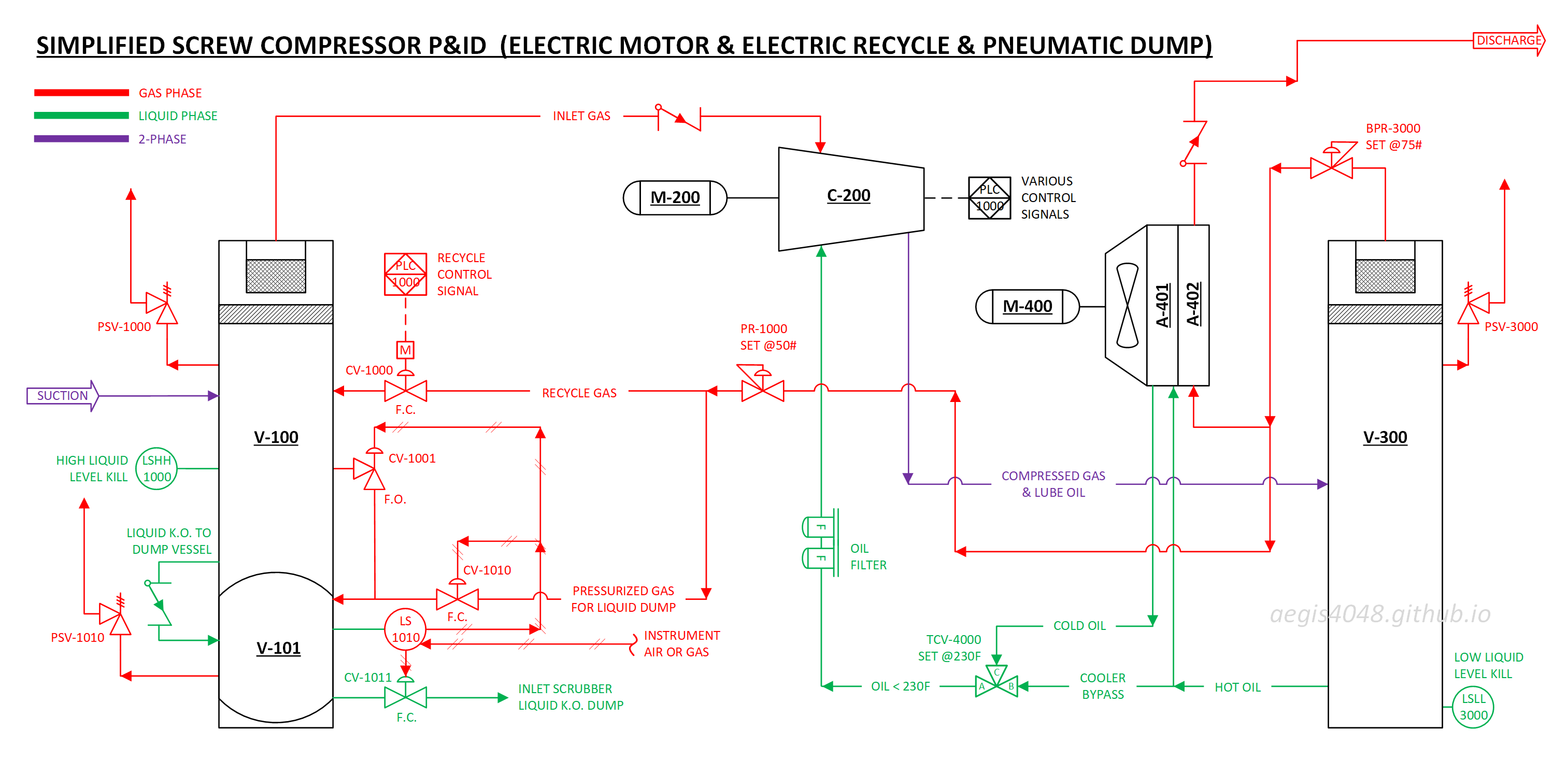
Type B: Electric/Pneumatic Dump/Electric Recycle
This is the 3rd popular model among the four. This configuration is partially electric. The compressor driver and recycle valve are electrically powered, but the liquid dump system remains pneumatic. This configuration is typically used when:
- The customer prefers an electric model over a gas engine to minimize carbon footprint.
- They don't have clean instrument air supply to (instead of natural gas) to operate pneumatic valves (most flow control valves vent used pilot gas, see Note 2).
- They do not want to operate an electric liquid dump system due to higher costs and maintenance efforts.
All conditions must be satisfied for this configuration to be chosen. For the recycle valve, pneumatic valves are cheaper and easier to maintain, but some operators avoid them because they vent exhaust pilot gas. As a result, an electric actuator is used to power the recycle valve.
The flow control valves for the pneumatic dump system has the same vent pilot gas issues. However, replacing them with an electric liquid pump is often not desirable due to higher costs and maintenance efforts compared to the competitive advantages of a pneumatic dump system. Therefore, a compromise is made by retaining the pneumatic liquid dump system while using an electric actuator for the recycle valve.
The key advancement over the previous fully electric model (Type A) is the blowcase system - a term derived from its function of using pressurized gas to "blow away" accumulated liquid. The blowcase replaces the electric pump by utilizing the compressor's readily available discharge pressure. When liquid in V-101 exceeds the LS-1010 setpoint, the system automatically initiates a dump cycle, using 30-50# gas from the V-300 discharge scrubber line to push out accumulated liquid. Rather than depending on external power, this design repurposes the compressor's existing energy, reducing maintenance costs and eliminating unnecessary electrical components. By making full use of already available pressure, the system delivers a more cost-effective solution. Refer to Section 6 for blowcase operation details.
One downside of this configuration stems from the pilot gas venting issues for the control valve operations. The pneumatically operated valves (CV-1001, CV-1010, and CV-1011) require 20-30 psi of supply gas (either instrument air or gas) to actuate their diaphragms, which is subsequently vented to atmosphere after each operation. While these vent lines could theoretically be connected to a closed disposal system, most field installations vent directly to atmosphere due to the additional piping complexity and cost involved. This venting becomes a continuous source of emissions, representing an environmental tradeoff of the blowcase system's otherwise efficient design. While these gas venting issues can be eliminated by installing an air compressor on site, this adds additional costs for both installation and maintenance of the air compressor, and instrument air line tubings.
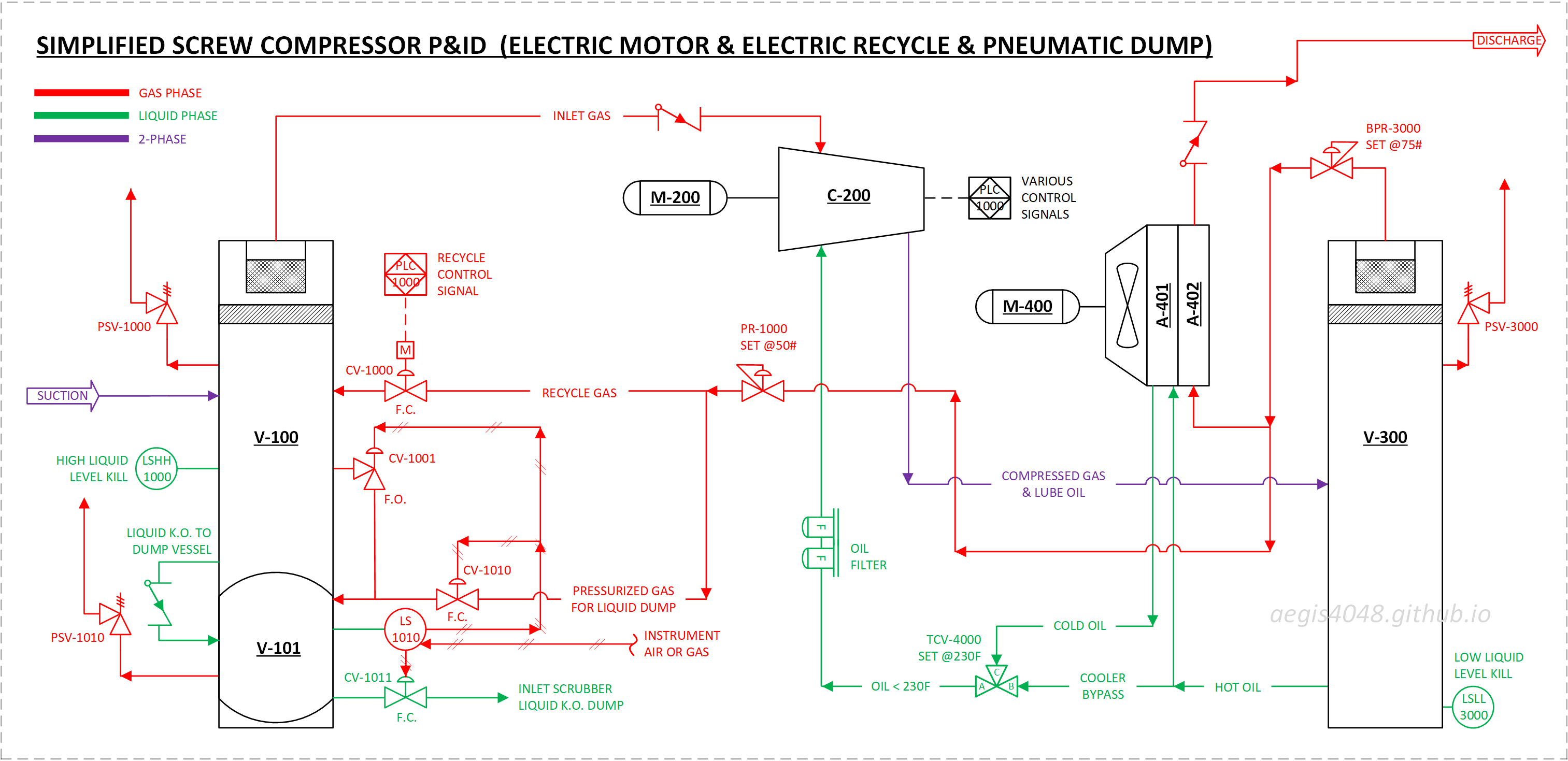
Figure 16: Simplified P&ID for electric motor driver for rotor + electric recycle valve + pneumatic liquid dump. Not all parts details are shown for simplicity.
Type C: Electric/Pneumatic Dump/Pneumatic Recycle
This is the most popular configuration due to rising concerns over emissions. The system uses a hybrid approach - while the compressor driver is electric, both the recycle valve and liquid dump system operate pneumatically. This configuration typically is used when:
- The customer prefers an electric model over a gas engine to minimize carbon footprint.
- The customer prefers an electric due to superior temperature (see Section 9) and RPM (see Section 8.2) control.
- The customer considers control valve vent gas emissions to be minimal.
- They do not want to operate an electric liquid dump system due to higher costs and maintenance efforts.
- They have clean instrument air supply to (instead of natural gas) to operate pneumatic valves.
If an air compressor exists on-site, the electric valve's sole advantage (emissions reduction) becomes irrelevant for compressor applications. Conversely, even without an air compressor, operators often accept the minimal control valve emissions rather than opting for electric recycle valves or liquid pumps due to maintenance cost. See Section 7.3 for solenoid valve working principles.
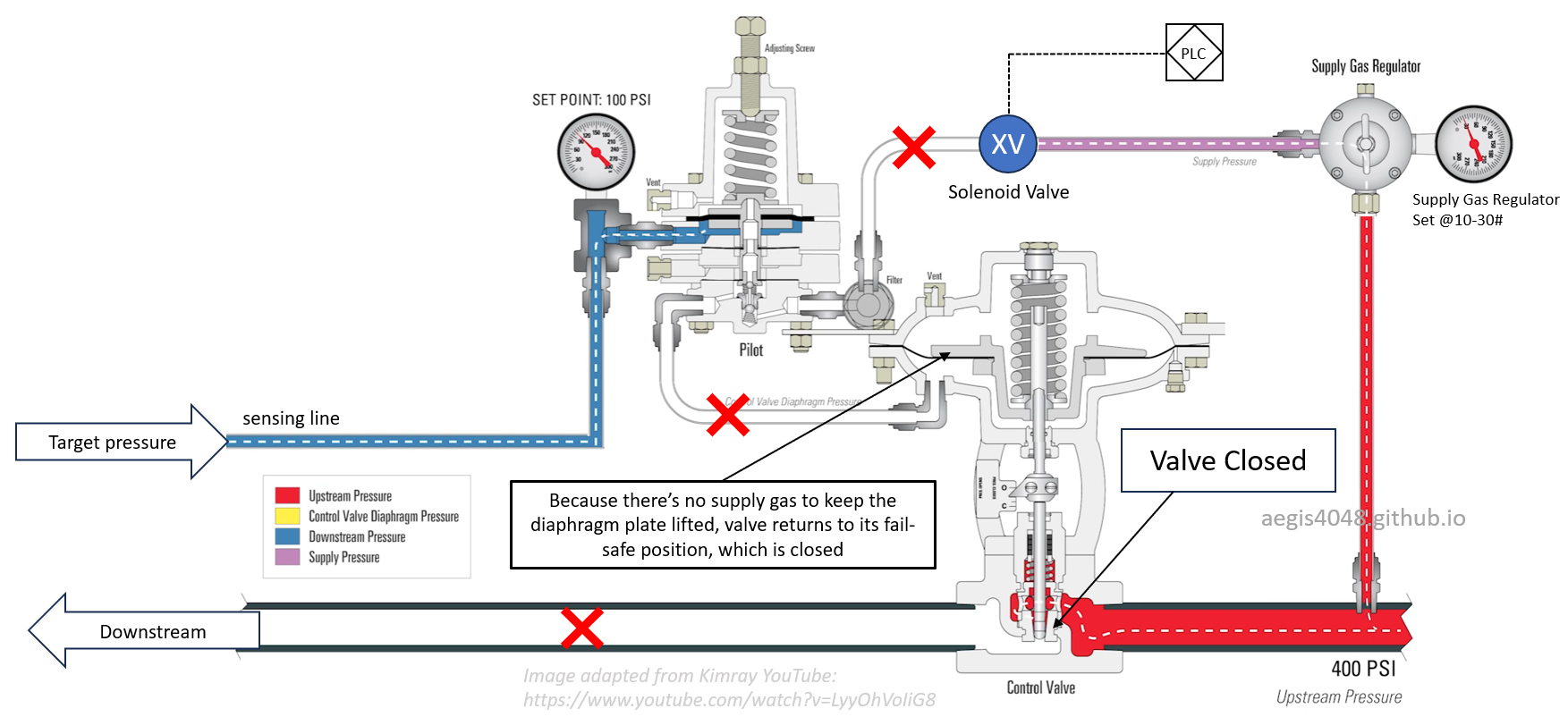
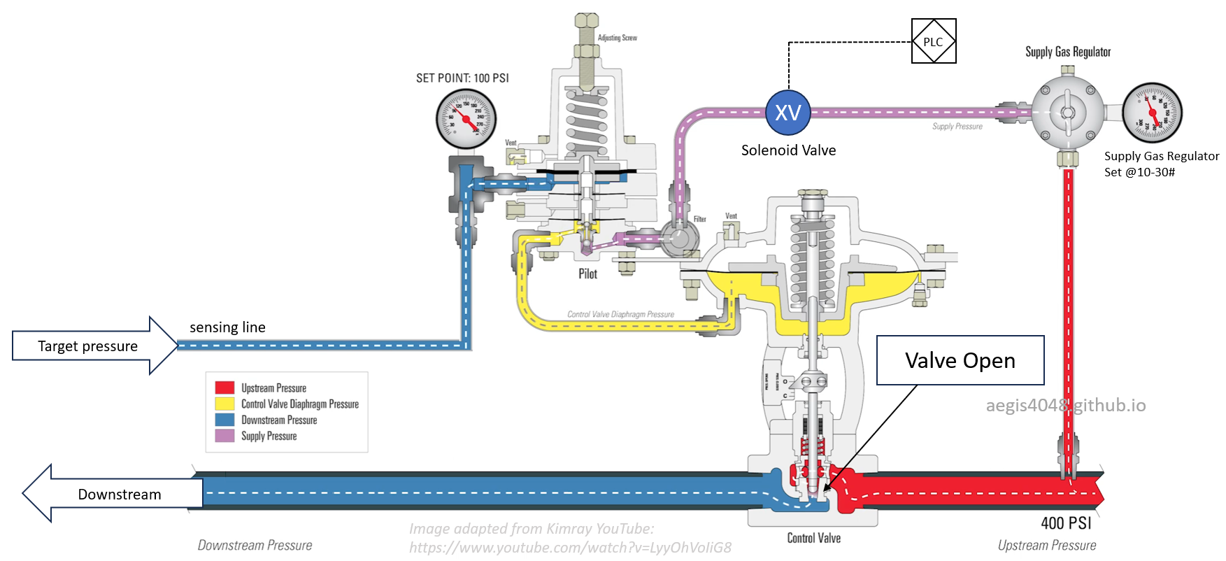
The main difference from Type B is the replacement of the electric recycle valve CV-1000 with a pneumatic version, chosen for its longer-lasting diaphragm valve that reduces maintenance compared to electric actuators. This modification requires adding a normally-closed solenoid valve XV-1000 on the pilot gas line since pneumatic valves cannot directly interpret electrical signals from PLC-1000. In normal operation, XV-1000 blocks pilot gas to CV-1000, keeping it closed. When PLC-1000 activates recycle mode, it energizes XV-1000 to open, allowing pilot gas to lift CV-1000's diaphragm and open the recycle valve.
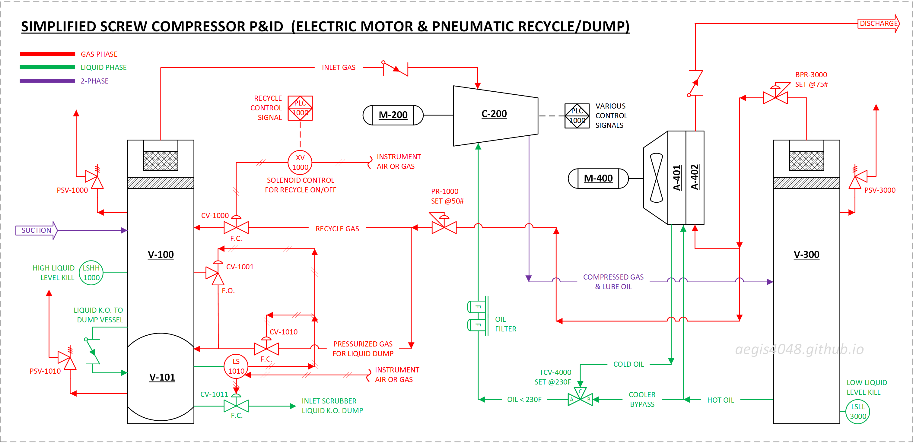
Figure 17: Simplified P&ID for electric motor driver for rotor + pneumatic recycle valve + pneumatic liquid dump. Not all parts details are shown for simplicity.
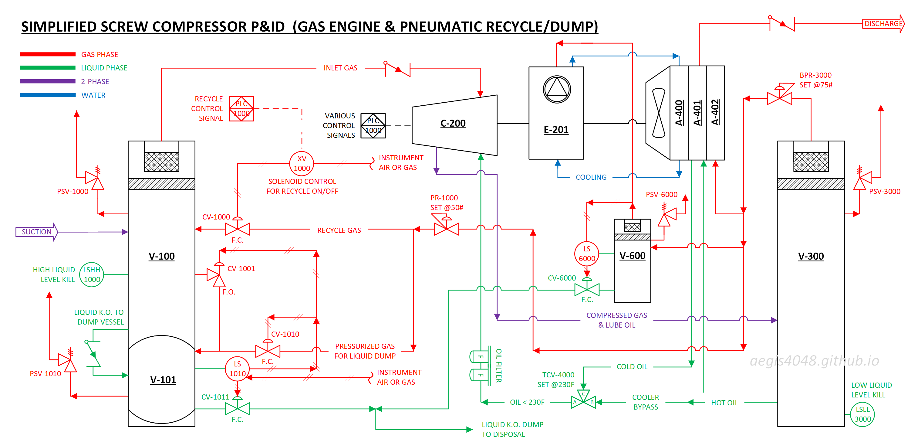
Type D: Gas Engine/Pneumatic Dump/Pneumatic Recycle
Finally the gas engine model. This is the 2nd most popular option. Engine units are the cheapest usually. Everything is powered by natural gas. This configuration typically is used when:
- Customer requires emissions control but lacks access to electric power (no alternative)
- Customer has electric power available, but source is high-emission (e.g., coal-fired plant), making gas engines environmentally preferable
- Customer does not consider emissions reduction a operational priority
- Customer's primary decision factor is achieving lowest operational costs
Meeting one of the conditions suffices for choosing this configuration. Gas engine models tend to be slightly cheaper than eletric models. Gas engines have inferior RPM (see Section 8.2) and temperature (see Section 9) control compared to electric models, but as long as they don't cause problems, engine units are preferred if the lowest operating cost is the main motivation.
The engine installation differs fundamentally from electric motors by requiring multiple support systems. First, combustion engine demands clean, dry fuel gas, achieved through the fuel pot scrubber (V-600) which removes any residual entrained liquids one more time after the discharge scrubber (V-300). Unlike the suction scrubber V-100, V-600 doesn't need a blowcase dump system - its position downstream of the compressor provides sufficient pressure for liquid removal, though it still requires a level switch (LS-6000) and dump valve (CV-6000) for automation.
Second, the engine cooling system uses a dedicated coolant loop to manage engine temperature. In Figure 13, the Flogistix FX12 model features a dedicated fan solely for engine coolant, while the lube oil and gas share a separate fan. In contrast, Figure 1 shows a single fan handling all three: coolant, lube oil, and gas. Like automotive engines, the system also includes engine oil for lubrication, which must be periodically refilled.
Third, the engine’s rotating shaft mechanically drives both the cooling fan and the compressor, eliminating the need for a separate electric motor for the fan. While this lowers the unit cost compared to electric models, it makes temperature control more difficult. Because fan speed is mechanically tied to engine RPM, it cannot be adjusted independently—it simply floats with the compressor RPM. See Section 9 for a detailed discussion on temperature control differences between engine-driven and electric units.
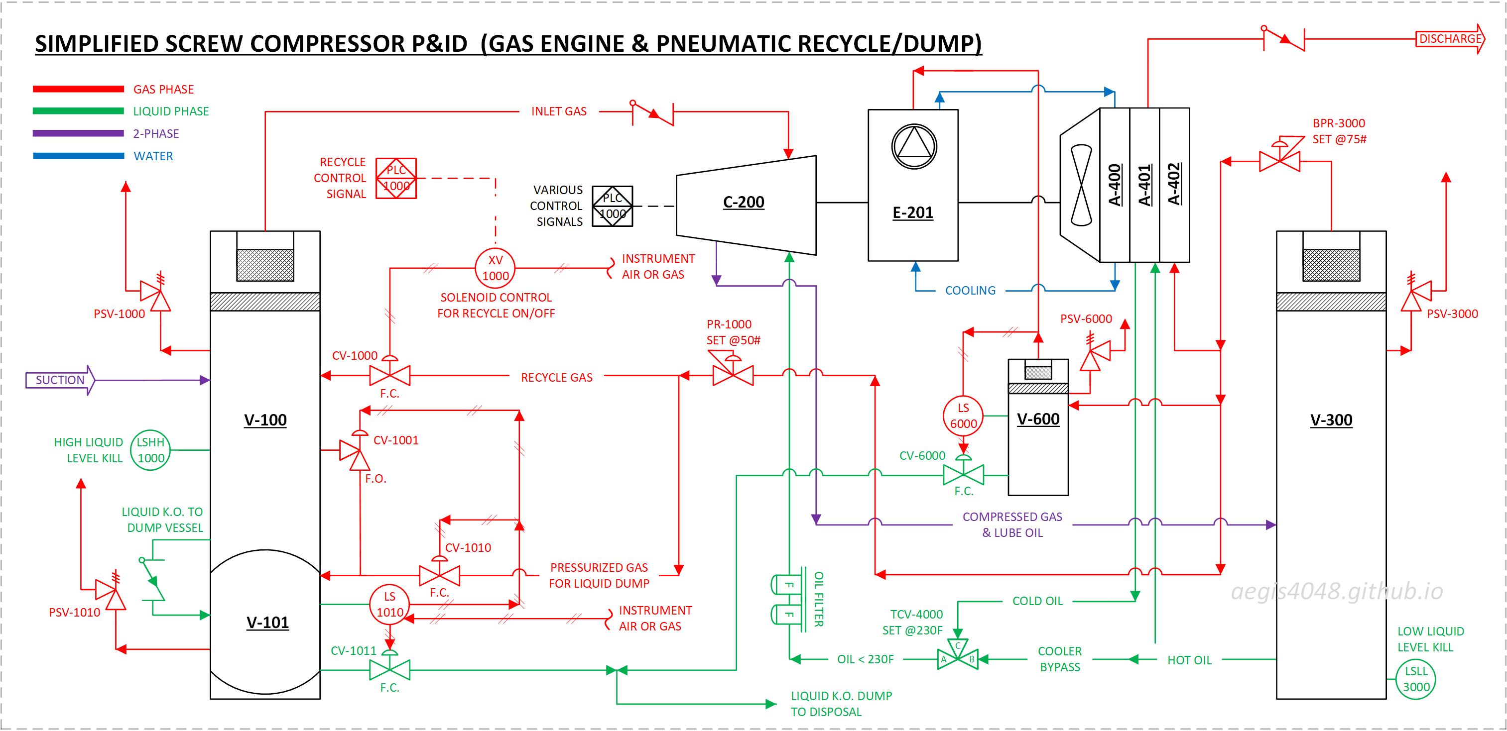
Figure 18: Simplified P&ID for gas engine driver for rotor + pneumatic recycle valve + pneumatic liquid dump. Not all parts details are shown for simplicity.
6. Pneumatic liquid dump cycle (blowcase)
The blowcase system solves the limitation of compressor suction scrubbers lacking pressure to dump liquid. These scrubbers separate gas and liquids - gas goes up while liquid falls to the bottom due to gravity. For liquid dumping, suction scrubbers differ from upstream separators because they lack sufficient pressure to dump liquid on their own. While oil-flooded screw compressors have a suction pressure range of 0-50 psig, vapor recovery applications on VRTs (1-5 psig) or atmospheric tanks (0-1 psig) don't reach the minimum 20-30 psig needed for autonomous liquid dumping.
Liquid from scrubbers is typically dumped to atmospheric storage tanks. The tank's inlet ports are located on its roof. These tanks are usually 20-25 ft tall, requiring the liquid to overcome both the vertical hydrostatic head (10.825 psi for 25 ft tank height × 0.433 psi/ft liquid denstiy) and additional pressure losses through piping and control valves. In practice, operators set dump pressures at 30-50 psig for reliable operation, which explains why upstream heater treaters maintain minimum 20-30 psig. Suction scrubbers usually don't have this much pressure.
In Figure 16, the blowcase (V-101) uses compressor discharge gas (60–350 psig from the V-300 discharge scrubber), regulated down via PR-1000 to stay below the blowcase’s MAWP (e.g., 125 psig). For typical vapor recovery applications where liquid is dumped to nearby storage tanks, a setpoint of 50 psig is sufficient and often used. However, if higher pressure is required—such as in wellhead setups where blowcase liquid is blended into a pressurized flowline (doesn't have to be this way, but it makes the field setup easier)—you'll need two separate regulators: one set at 110 psig for the blowcase, and another below 50 psig for the recycle line. In Figure 16, PR-1000 regulates both lines at 50 psig, but in this scenario, PR-1000 would be set at 110 psig, with a second regulator installed on the recycle line at 50 psig to reduce its pressure (to prevent high HP shutdown, a compressor's mechanical limit on suction is at 50 psig).
When the liquid level in the blowcase exceeds the level switch LS-1010 setpoint, the system automatically initiates a dump cycle, using this regulated gas pressure to push out accumulated liquid. This "blow away" function gives the system its name and provides a solution that uses existing system pressure rather than requiring additional power sources such as eletric liquid pumps, such as in Figure 34.
Read the below Liquid Dump Cycle Order in conjunction with Slideshow 2 for better understanding of the dump cycle.
Slideshow 5 also provides good animation slides to understand liquid dump valve opration.
Liquid Dump Cycle Order
- Insufficient liquid in V-101 to trigger dump cycle. LS-1010 remains closed, blocking instrument supply gas. Without supply pressure, fail-close valves (CV-1010 and CV-1011) remain closed while fail-open valve (CV-1001) stays open. Pressure equalizing valve CV-1001 maintains pressure equilibrium between V-100 and V-101 for continuous gravitational liquid flow from V-100 to V-101 (see Note 1). Liquids accumulate in V-100.
- Liquid level reaches threshold. LS-1010's floating element triggers at high level (see Section 7.5 for level switch operation).
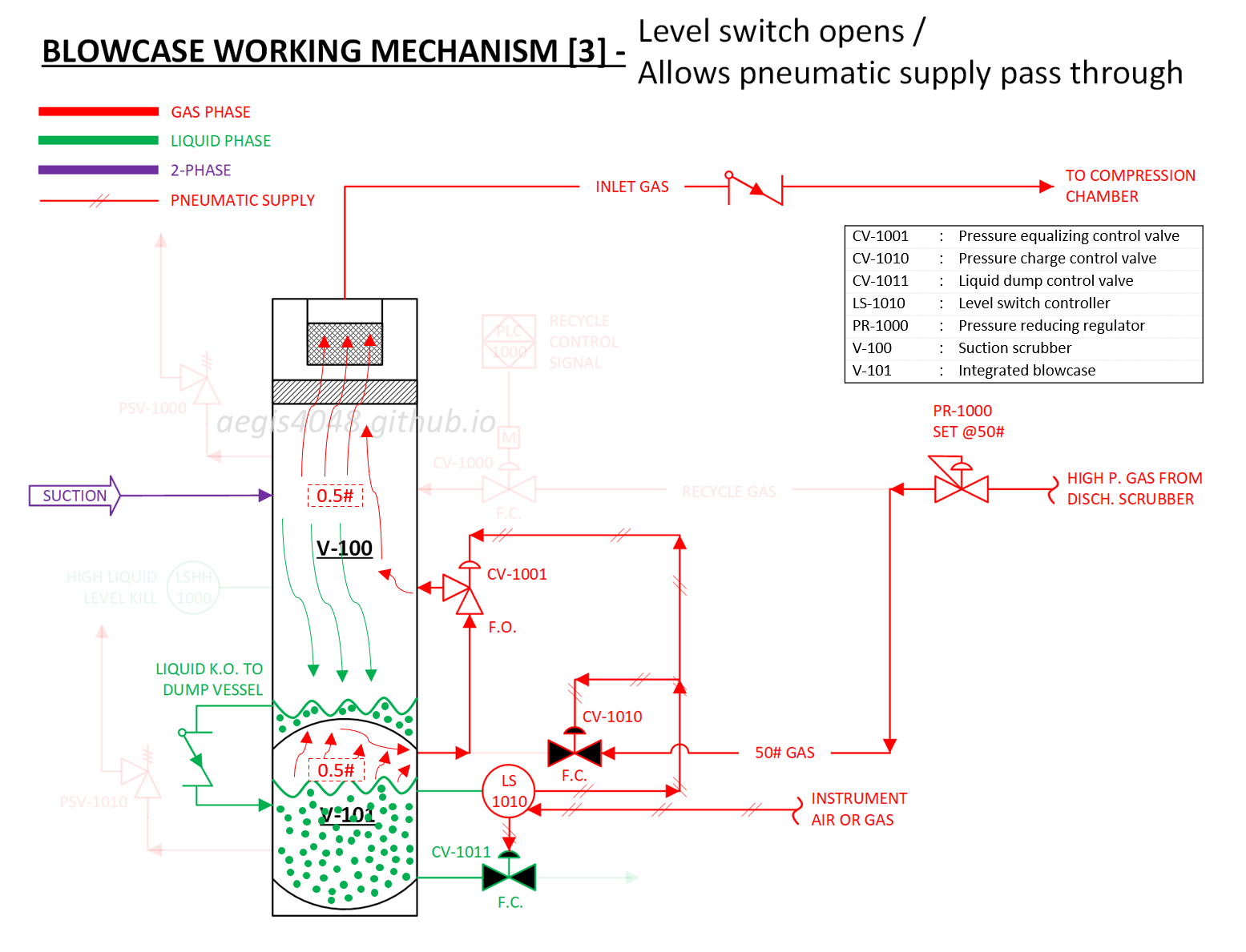
- Level switch opens, allowing pneumatic supply (instrument air/gas at 20-30 psig) to pass through. This is the recommended diaphragm working pressure range for the liquid control valves.
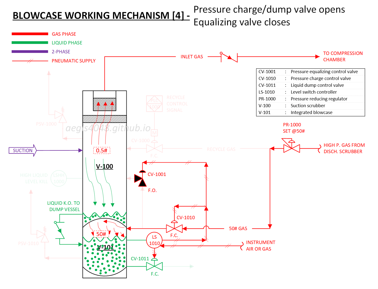
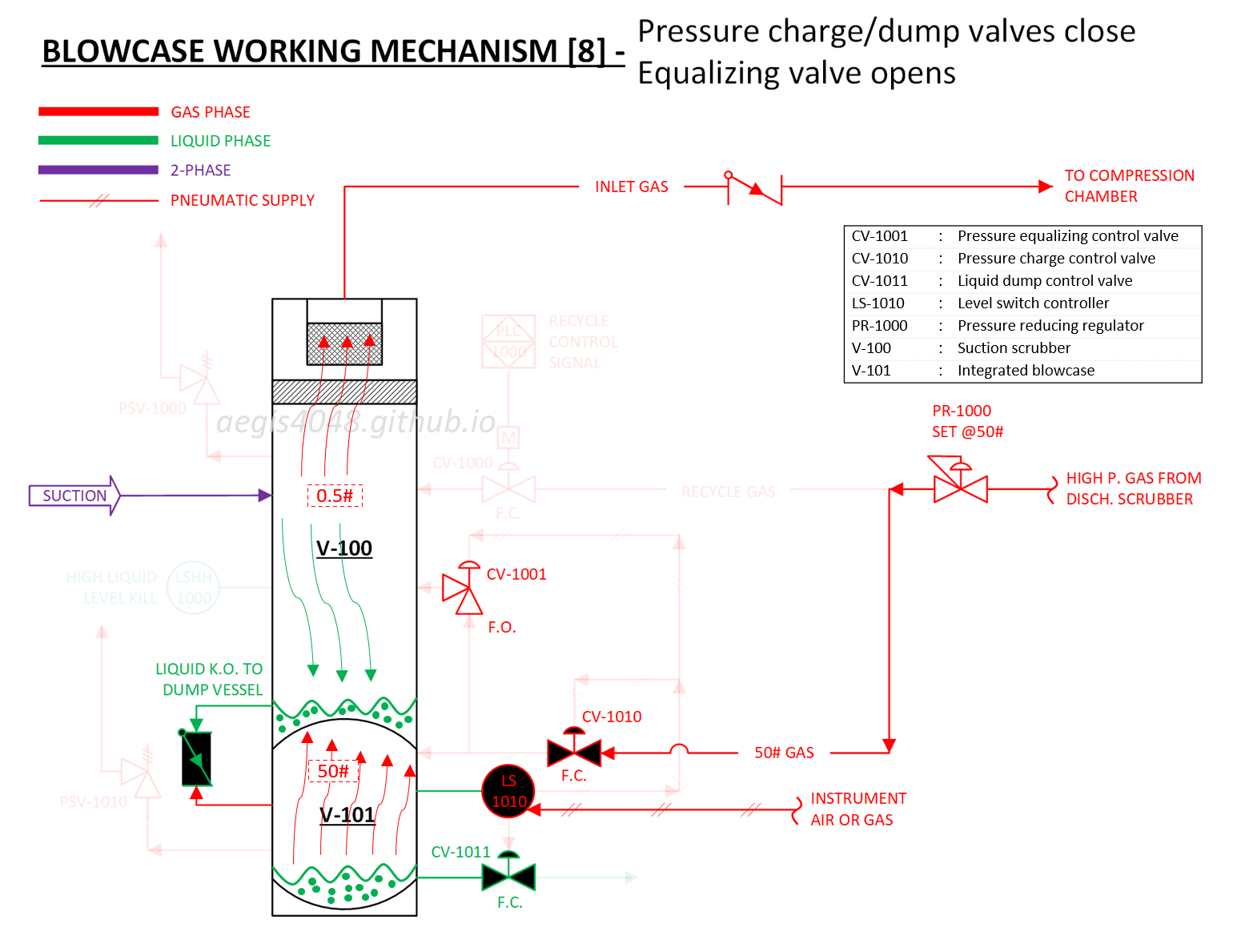
- Pneumatic supply enters diaphragm chambers of CV-1001, CV-1010 and CV-1011. CV-1001 closes (fail-open design). CV-1010 and CV-1011 open (fail-close design). Pressure charge valve CV-1010 admits 20-50# blowdown gas into V-101. The drain line check valve closes to prevent high-pressure backflow to V-100. With CV-1001 closed, V-101's vapor space pressurizes due to lack of relief point.
- V-101 vapor pressure exerts downward force on liquid surface. With liquid dump valve CV-1011 open, liquid flows through dump line to relieve pressure.
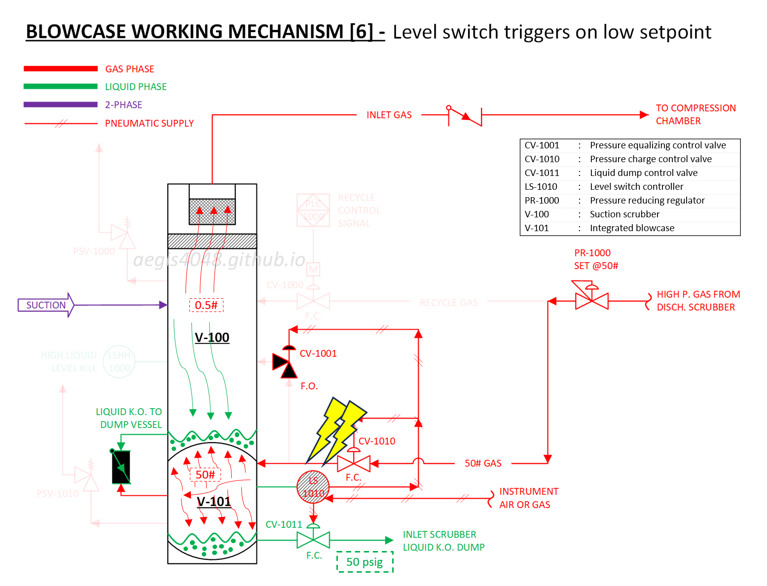
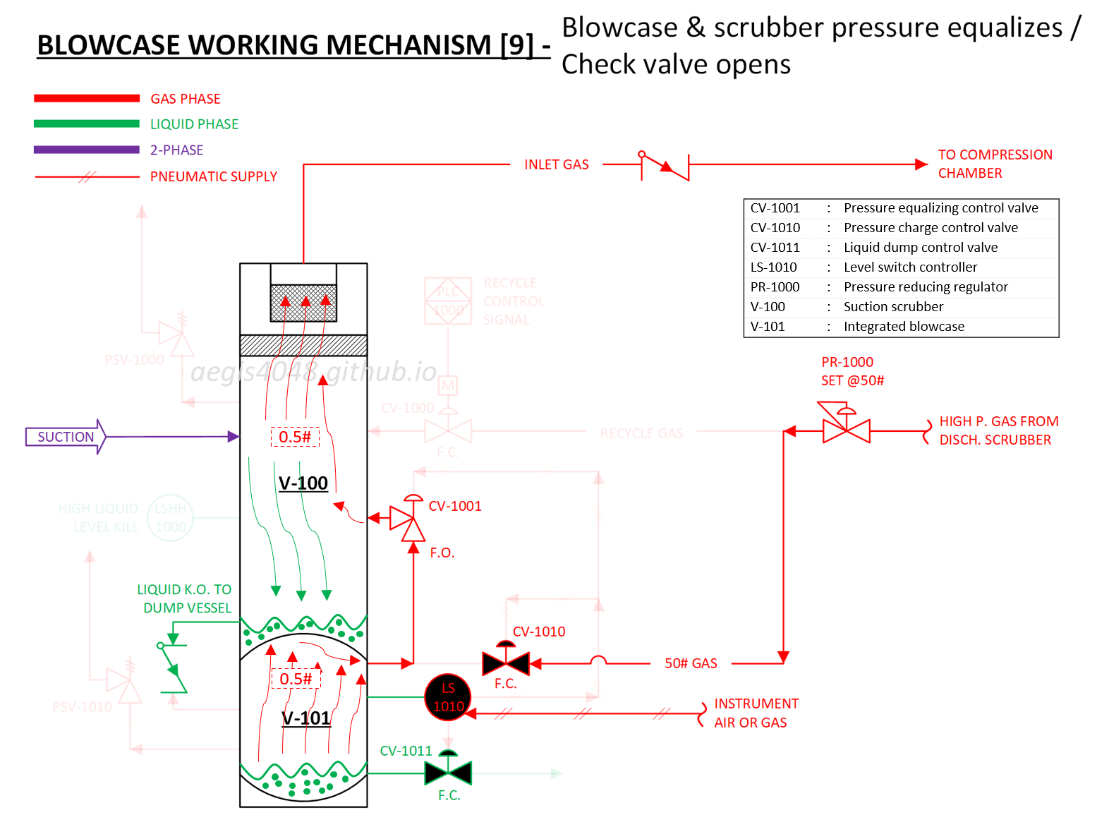
- Liquid level drops sufficiently. LS-1010's floating element triggers at low level (see Section 7.5 for level switch operation).
- LS-1010 closes, cutting off pneumatic supply.
- Pneumatic supply "fails". CV-1001 (fail-open) opens. CV-1010 and CV-1011 (fail-close) close.
- With CV-1001 open, V-101 vapor space pressure equalizes with V-100. Check valve opens.
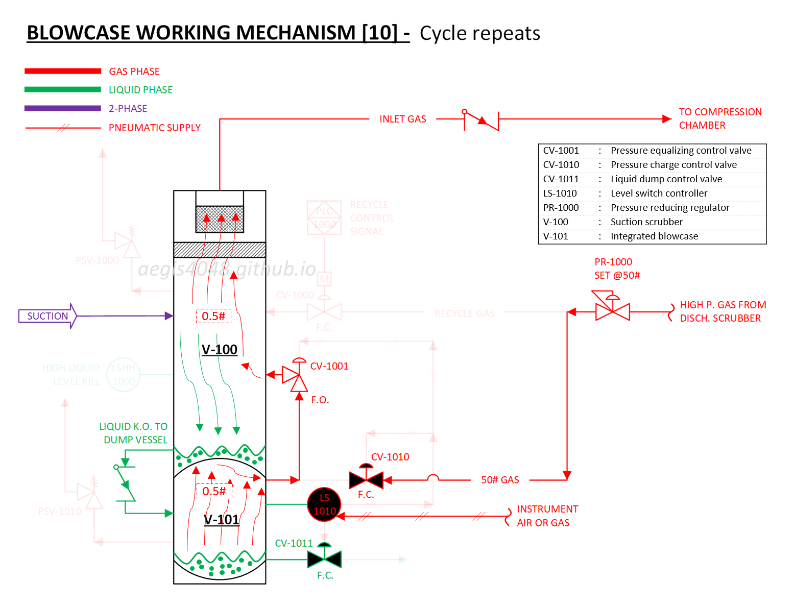
- Liquid resumes draining from V-100 to V-101. Cycle repeats.
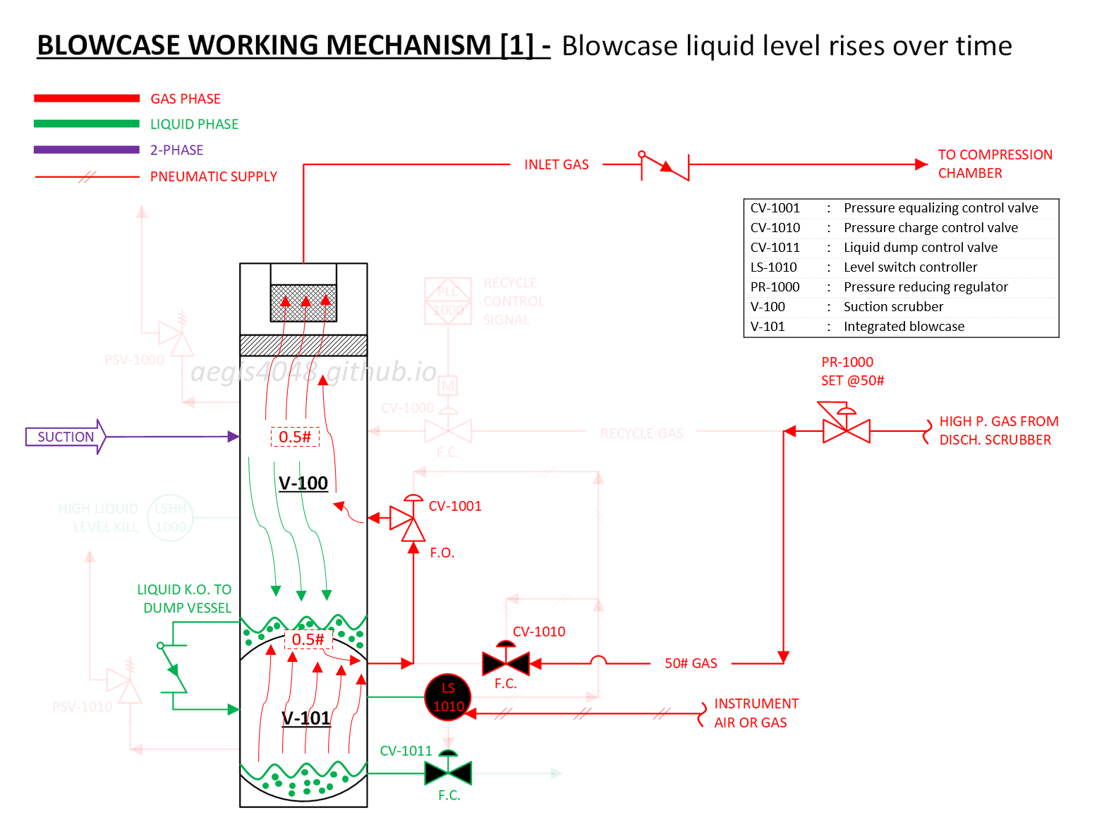
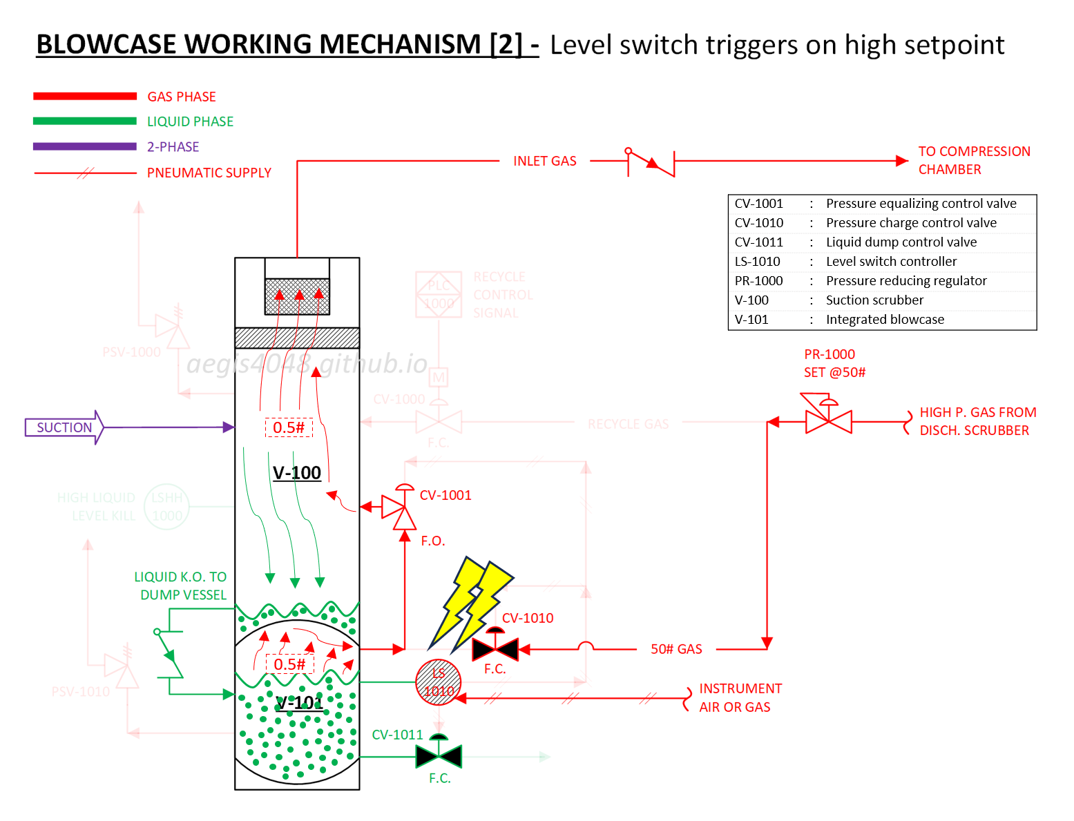
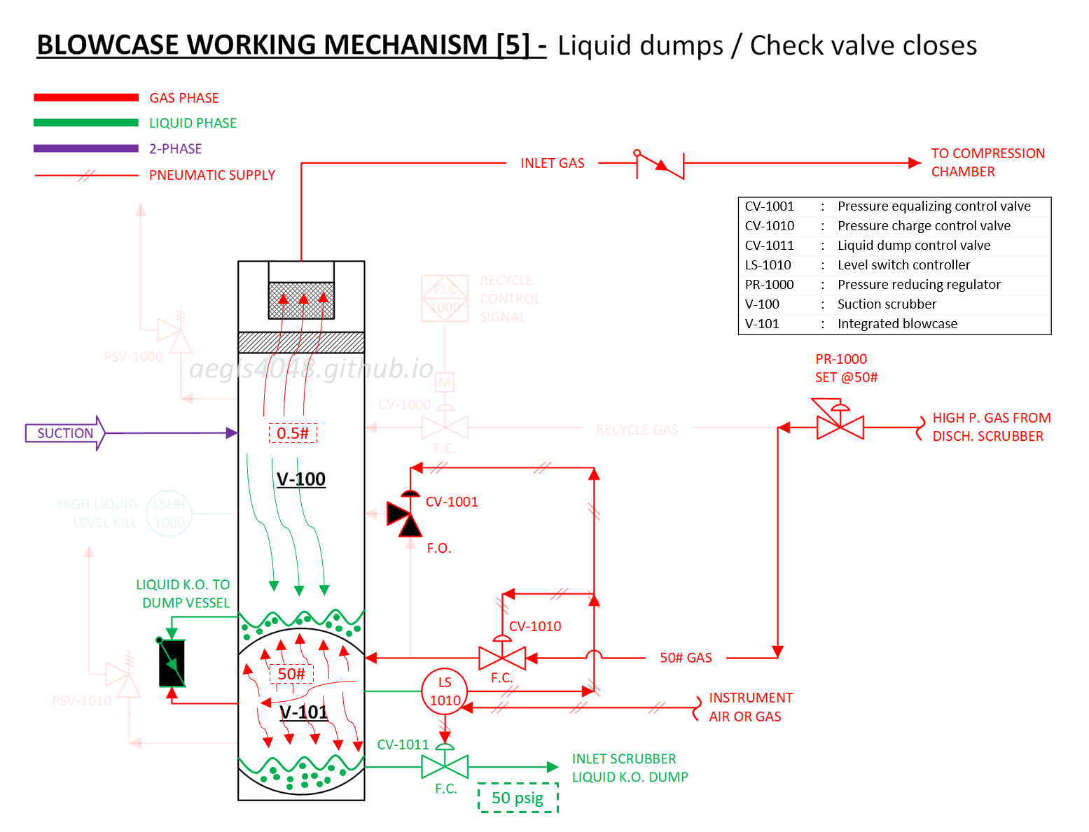
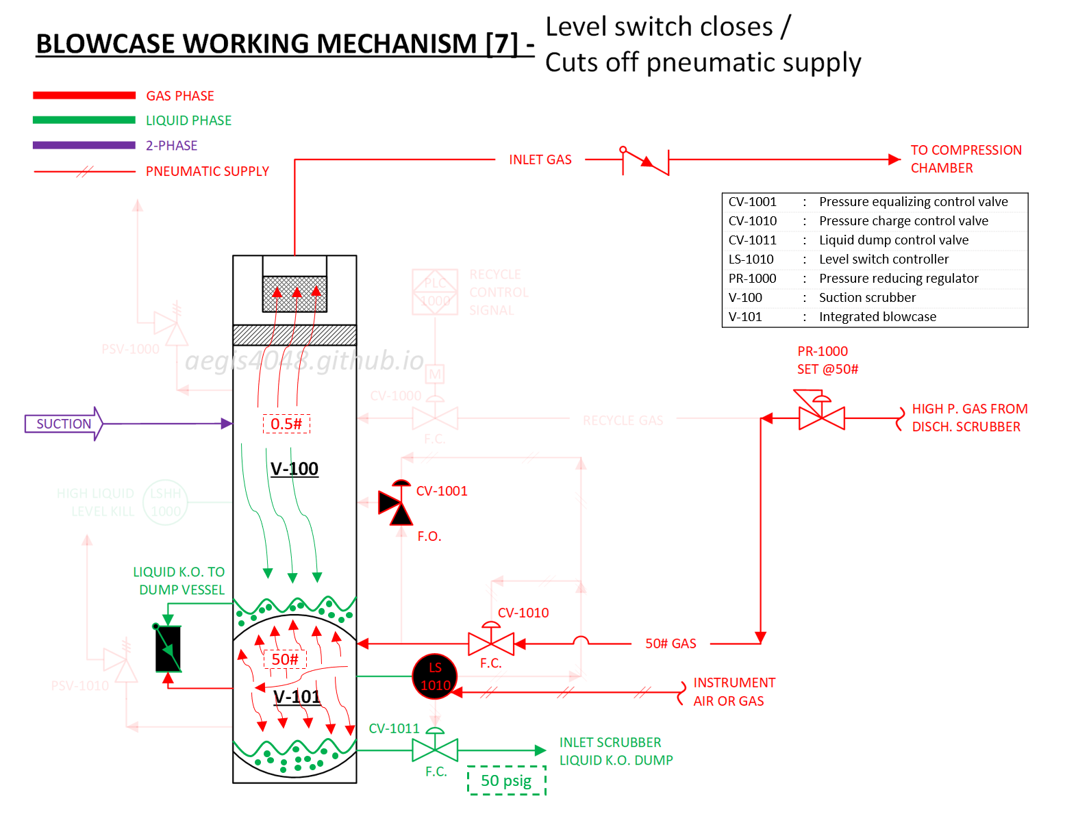
Slideshow 2: Demonstrates the liquid dump cycle of an integrated blowcase (V-101) system inside a suction scrubber (V-100) using pressurized gas blowdown. The cycle initiates when the liquid level exceeds the level switch controller's (LS-1010) setpoint. During operation, 1) Pressurized gas (30-50 psig range) enters from the discharge scrubber, 2) The gas forces the liquid out through the dump line, and 3) The cycle completes when the liquid level falls below the setpoint. Note that the systems that are not part of the liquid dump cycle (recylce, PSVs, PLC, high level kill switch) are hidden with 90% transparency for enhance reader's understanding.
Note 1: Pressure equalizing valve (CV-1001)
The pressure equalizing valve (CV-1001) plays a critical role ensuring the gravitational flow of liquid knockouts from suction scrubber (V-100) to blowcase (V-101) through the downward-sloping piping with a check valve.
In Slideshow 2, when dump cycle is off, liquid continues to flow downward from V-100 to V-101 due to gravity. CV-1001, an equalizing valve, maintains pressure equilibrium between V-100 and V-101. CV-1001 remains open during this phase—it is fail-open, meaning it stays open in the absence of pneumatic supply. The purpose of CV-1001 being open is to ensure the gravitational flow of liquid from V-100 into V-101. Assume the downward-sloping pipe between V-100 and V-101 has a 1-ft height difference between the inlet and outlet. With a liquid density of 0.433 psi/ft in the suction scrubber, a 0.433 psi gravitational hydrostatic head drives the liquid from V-100 into V-101. If some of the liquid in V-101 vaporizes (highly likely due to the volatile nature of the liquids for compressor applications) because of conditional changes, the vapors accumulate and pressurize V-101. While the check valve prevents these volatile vapors from backflowing into V-100, the liquid accumulating in the suction scrubber will be unable to flow downward into V-101 due to the higher pressure vapors of V-101 blocking the other side of the check valve. It is important to note that the absence or failure of CV-1001 can trigger a high-level kill (LSHH-1000) because the liquids in V-100 cannot flow down to V-101.
When dump cycle is on, CV-1001 is closed to ensure the blowdown gas pressure is directed only to V-101 and to liquid dump destination, preventing pressure from being dissipated into V-100.
7. Control Devices Working Mechanisms
7.1. Electric flow control valve
Electric flow control valves operate on a straightforward principle. Consider the recycle valve shown in Figure 19 and 20 as an example. The valve opens when receiving an electric signal from the PLC to initiate recycle mode.
The valve consists of three primary components: the electric motor which provides driving power, the linear adapter that transfers power to the piston for opening/closing the valve, and the valve body which controls the flow of target fluid.
The key advantage over pneumatic control valves is zero emissions since it doesn't vent supply gas after each operation on/off. However, this comes with trade-offs: the motor costs more than a pneumatic diaphragm actuator and requires more frequent maintenance.
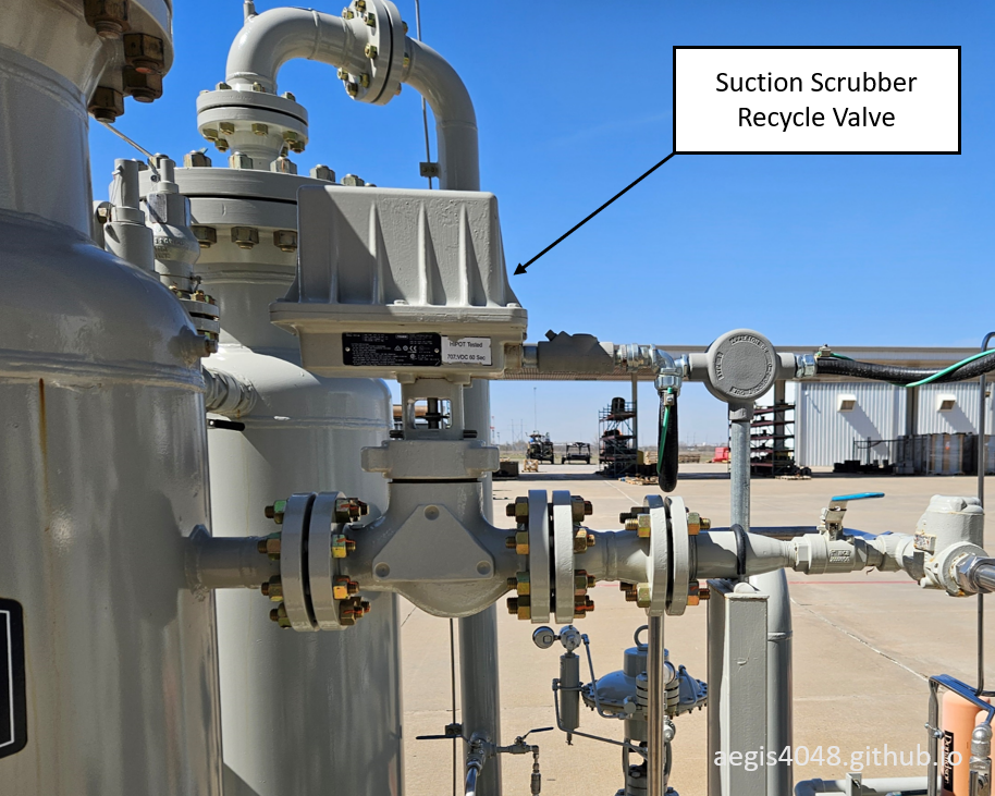
Figure 19: Electric actuator recycle valve for oil-flooded screw compressor suction scrubber (CV-1000 in Figure 16).
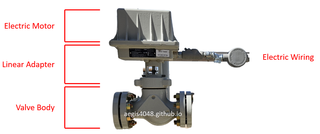
Figure 20: Electric flow control valve components showing the motor (provides power), linear adapter (transfers to piston), and valve body (controls fluid flow) (CV-1000 in Figure 16).
7.2. Pneumatic flow control valve
The working principles of pneumatic control valves are more complex than their electric counterparts. Take a look at the fail-close pneumatic recycle valve (CV-1000) shown in Figure 21 and 22. The pneumatic valves differ from electric types in two primary ways: they lack an electric motor and instead feature a pneumatic supply line. The piston movement mechanism also differs significantly - where electric valves use motor power to directly drive the piston, pneumatic valves rely on supply pressure acting on a diaphragm plate. This pressure exerts force on the diaphragm, which moves upward or downward depending on the configuration, and this motion is transferred to the piston through their mechanical connection.
Figure 23 shows a pressure equalizing valve (CV-1001). This is a fail-open type valve. The valve stays open in the absence of pressure supply. When supply pressure is present, the pressure enters from the top-side of the diaphragm chamber, and pushes down on the diaphragm plate and the piston, closing the valve.
Figure 24 and 25 illustrate fail-close (FC) and fail-open (FO) valve configurations. The "fail" condition occurs when pressure supply is lost, either through mechanical failure of supply lines or intentional cutoff for process control. Valve selection between FC and FO depends primarily on safety considerations - determining whether the safer failure state is open or closed for the specific application. Secondary considerations include existing piping configuration and process requirements.
A key limitation of pneumatic control valves is their inability to directly receive electric signals. This necessitates installing a solenoid valve in the pneumatic supply line to interface with electronic control systems. The solenoid valve converts electrical signals from the control system into pneumatic actions. Detailed specifications of solenoid valves are covered in Section 7.3.
Note that the liquid dump valves (CV-1011 and CV-6000) shown in Figure 18 are also pneumatic-type flow control valves too.
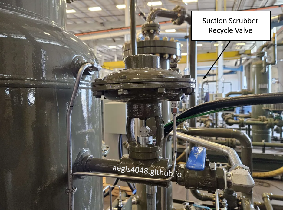
Figure 21: Fail-close pneumatic recycle valve (CV-1000 in Figure 18) installation for oil-flooded screw compressor suction scrubber. The valve is in closed position.
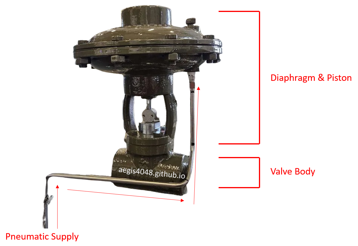
Figure 22: Fail-close pneumatic recycle valve (CV-1000 in Figure 18) components showing fail-close mechanism. The diaphragm-piston assembly connects to the valve body. Supply pressure lifts the diaphragm to open the valve (piston moves upward). On pressure loss, the piston returns to its fail-safe closed position. Pneumatic supply control is achieved through either a solenoid valve (electric signal) or pilot valve (pressure signal). Shown in closed position.
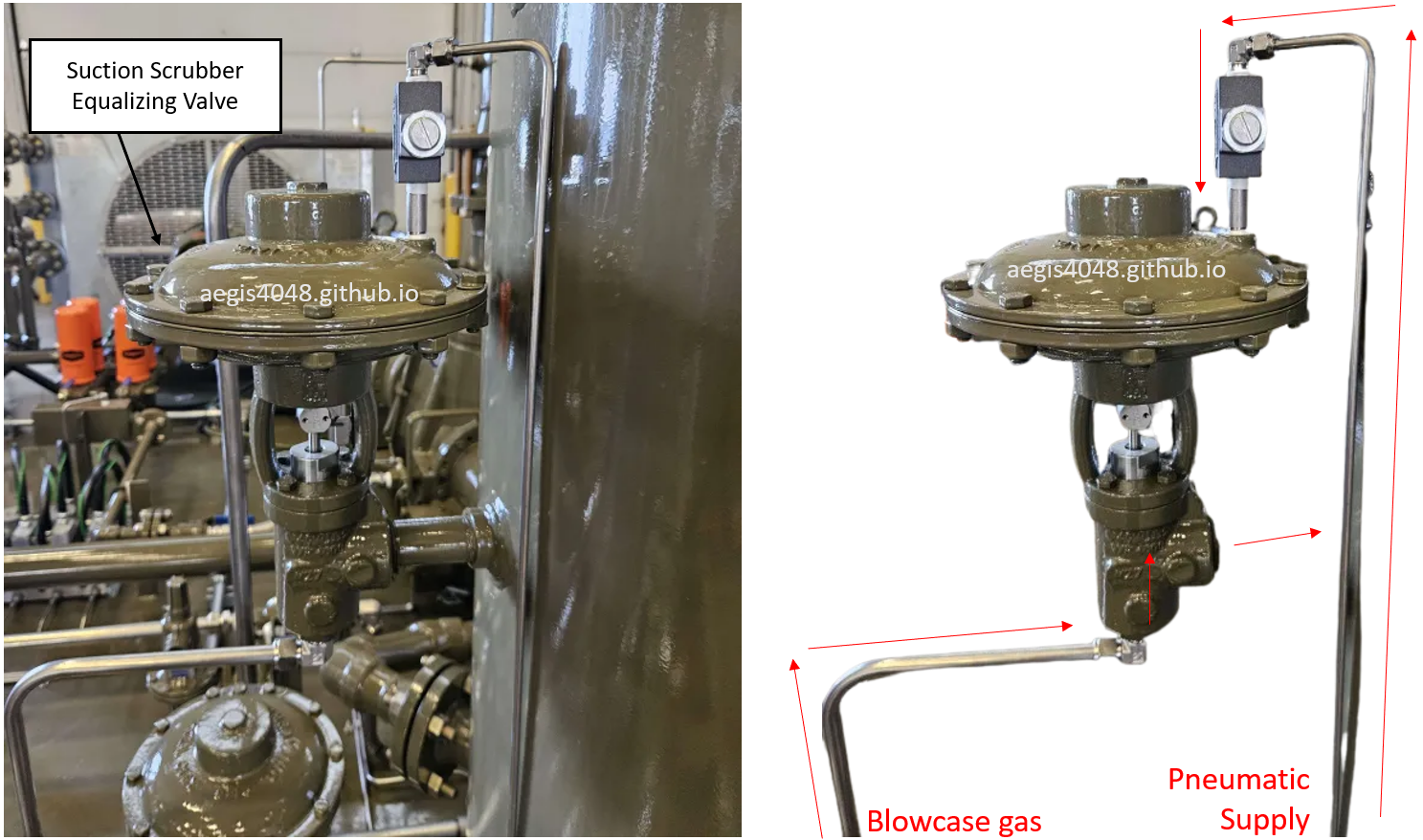
Figure 23: Fail-open pneumatic equalizing valve (CV-1001 in Figure 18, angled-body) installation for oil-flooded screw compressor suction scrubber. Pressure supply enters from the top-side of the pancake to press down on the diaphragm plate, closing the piston. Loss of supply pressure opens the valve. Shown in open position. The silver rectangular object mounted on top of the pancake on the pneumatic supply line is a proportioning valve, which allows gradual entrance of pneumatic supply to prevent the valve from diaphragm plate from slamming shut open/close.
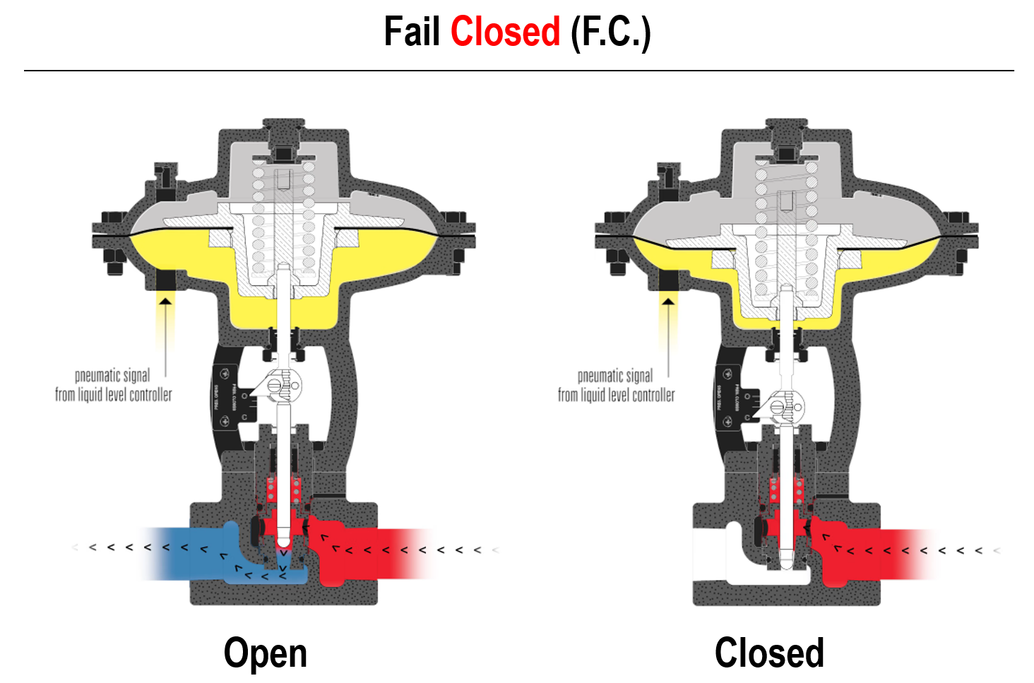
Figure 24: Illustration of fail-close valve. The valve closes on absence ("fail") of pressure supply. Image adapted from: Kimray video
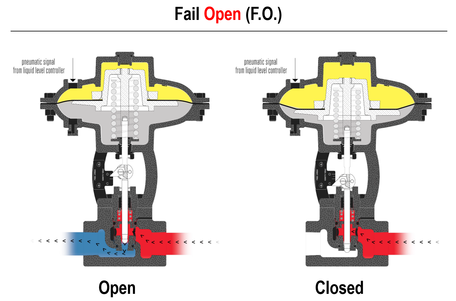
Figure 25: Illustration of fail-open valve. The valve opens on absence ("fail") of pressure supply. Image adapted from: Kimray video
7.3. Solenoid valve
Solenoid valves are essentially an electric control adapters for pneumatically operated valves. It solves the problem of pneumatic valves' inability to read electric signals from a computer. These valves correspond to XV-1000 in Figure 18. See Figure 26 below for a representative solenoid valve diagram. Note that the venting of residual pressure between the diaphragm chamber of a flow control valve and the [CYL] port of a solenoid valve is a source of emissions (see Note 2) when natural gas is used for pneumatic supply, instead of air compressors.
For demonstration, consider solenoid installation on the pneumatic supply line for the recycle valve CV-1000:
-
Energized State (Recycle Mode Active):
PLC sends electric current through solenoid wiring
Current creates magnetic field around coil
Plunger lifts upward, opening flow passage
Pneumatic supply flows from IN port to CYL port
Supply pressure activates control valve diaphragm
Diaphragm lifts piston, opening recycle valve CV-1000
-
De-energized State (Recycle Mode Stopped):
PLC cuts power to solenoid
Plunger returns downward via spring force
Main supply path (IN to CYL) seals shut
Residual pressure vents through EXH port
Control valve returns to fail-safe position
Diaphragm falls with piston. CV-1000 fully shuts
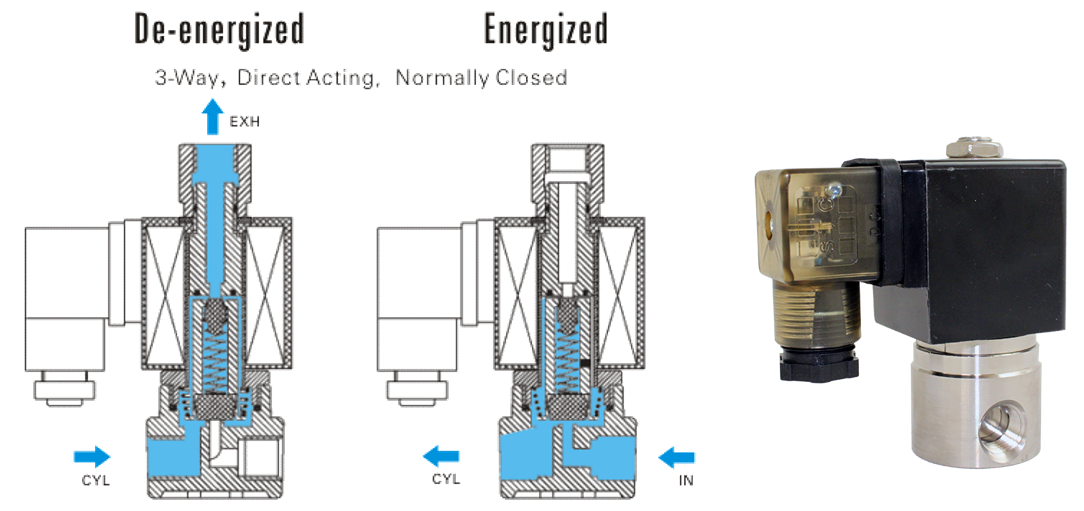
Figure 26: An example of a 3-way solenoid valve. [IN] is the inlet. [CYL] is the outlet. [EXH] is the pressure vent port when the solenoid gets close signal from a computure. Image adapted from: STC valve
While the illustration above shows a 3-way solenoid valve, a 2-way solenoid can also be used in certain setups. Unlike 3-way solenoids, 2-way valves lack a dedicated vent port—so the downstream control device must include its own venting mechanism. For instance, the suction control valve pilot in Figure 42A has a built-in vent port. In this case, a 2-way solenoid installed on the supply pressure line to the pilot is sufficient, as any residual pressure in the control valve diaphragm chamber can still be vented through the pilot’s vent port.
Another application of solenoid control is in well pad emergency shutdown (ESD) systems. Level gauge sensors monitoring oil/water tanks and pressure transmitters (PTs) installed on separators serve as monitoring devices. When these instruments detect out-of-control conditions, they send emergency signals through electrical wiring to the facility control panel. The system responds by activating a fail-close pneumatically operated shutdown valve (SDV) at the wellhead. This activation occurs when the solenoid interrupts the pneumatic supply pressure that normally keeps the SDV's diaphragm lifted. With the pressure supply cut off, the diaphragm releases and the valve returns to its fail-safe closed position. This automated emergency action prevents hazardous situations including and separator ruptures that could result from overpressure conditions and tank overflows.
Slideshow 3 below illustrates the solenoid installation in the pneumatic supply line to the control valve pilot. This specific configuration shows a suction control valve (see Section 7.9), which is a type of a fail-close pilot-operated pressure reducing regulator. In standard operation without the solenoid, the mounted pilot on the top left maintains primary control of pneumatic supply flow based on downstream pressure requirements. The solenoid installation introduces secondary electronic control that can override the pilot's pressure-based regulation when computer intervention is required.
Slideshow 3: Illustration of a solenoid valve inturruption on a fail-close pilot-operated pressure reducing regulator. Image adapted from: Kimary video.
7.4. 3-Way thermostatic valve
Oil-flooded screw compressors use a 3-way thermostatic valve to control lube oil injection temperature. The lube oil enters the compression chamber, mix with the process gas, and absorbs heat of compression. The 2-phase mixture leaving the chamber pickups 5-15°F increase in temperature (except during recycle mode, see Section 8.3). This temperature maintains the operating temperature of the whole unit.
Figure 27 shows a typical installation on an electric compressor (the setup is the same for gas engine models). Inside the valve is a thermal element that expands or contracts in response to temperature, adjusting its position to regulate oil flow (see Figure 27A. The valve maintains a target temperature at the outlet (A-port) by blending hot bypass oil from the B-port with cooled oil from the C-port. The thermal element determines the proper mixing ratio between the hot bypass oil and cooled oil. These valves are usually set anywhere between 200-250°F depending on applications. The element must be physically swapped in the field to change the setpoint—there are no adjustable screws or dials. See Figure 27B and C for pictures of the thermal elements.
Assume a 230°F setpoint with a ±3°F tolerance. The illustration below shows how the valve responds under different scenarios based on incoming oil temperature and cooler performance.
-
Incoming oil is above 230°F (e.g., 250°F) and the cooling fan succeeds (e.g., delivers 210°F):
The valve partially opens both the B-port (bypass) and the C-port (cooler) to blend the hot 250°F bypass oil with the cooled 210°F oil. This mixing balances the streams to achieve the 230°F setpoint at the A-port. The thermal actuator dynamically adjusts the flow proportions, ensuring neither B nor C is fully closed under ideal cooling conditions. Example process simulation of this operation is shown in Slideshow 4. For the 250°F incoming oil scenario, 84% of bypass cooler (B-port) and the remaining 16% was cooled to 122°F (C-port) and achieved 230°F temperature at the A-port.
-
Incoming oil is above 230°F (e.g., 250°F) and the cooling fan fails (e.g., only cools to 240°F):
The valve fully closes the B-port (bypass) and fully opens the C-port to rely solely on the cooled path. However, since the cooled oil is still above the 230°F setpoint, the outlet temperature at the A-port will stabilize above target (e.g., 240°F). This scenario indicates the cooling fan is undersized or overloaded. High temperature shutdown is likely to trigger.
-
Incoming oil is below 230°F (e.g., 210°F):
Since the oil is already below the 230°F setpoint, the valve fully closes the C-port (cooler) and fully opens the B-port (bypass). All flow is diverted through the bypass to avoid unnecessary cooling. The outlet temperature at the A-port will match the incoming temperature (210°F), and no mixing is performed. This indicates insufficient heat of compression generated due to lack of gas volume.
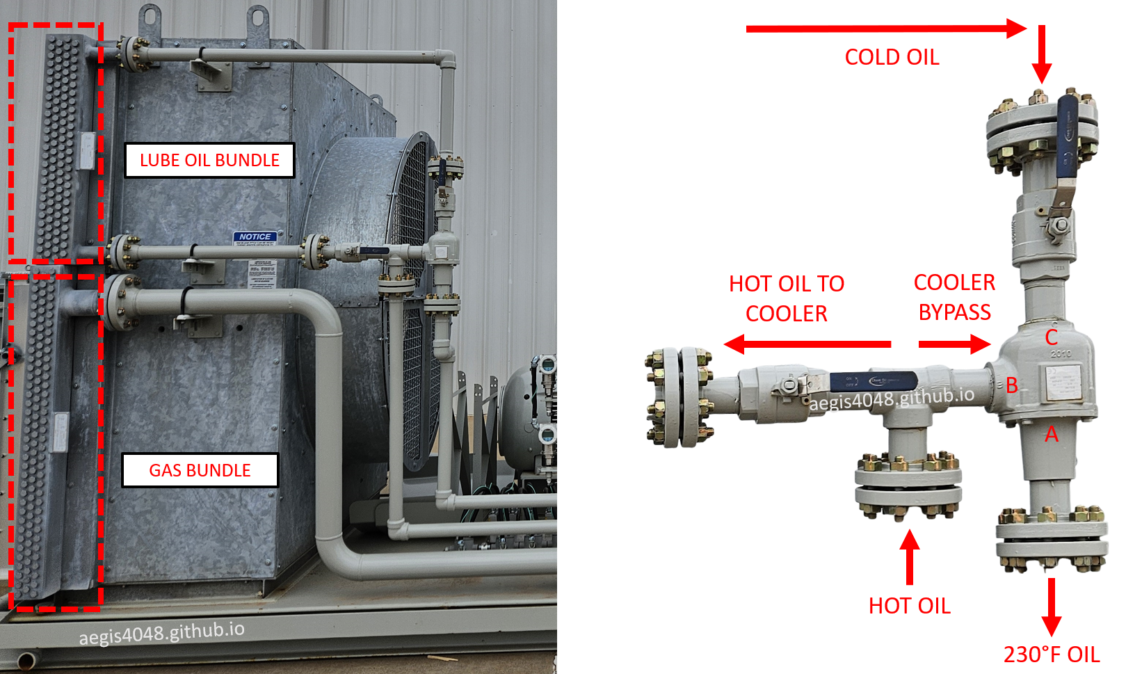
Figure 27: 3-way thermostatic valve installation on an electric oil-flooded screw compressor skid. Left side shows the connected piping and air cooler. The upper fan bundle handles oil cooling (connected to the thermostatic valve), while the lower bundle handles gas aftercooling (unrelated to the valve). The valve's internal thermal expansion element automatically adjusts to maintain the A-port outlet temperature at its factory-set point (typically 200-250°F). The thermal element position determines the mixing ratio between hot bypass oil (entering through B-port) and cooled oil (entering through C-port). Changing the temperature setpoint requires field replacement of the thermal element.
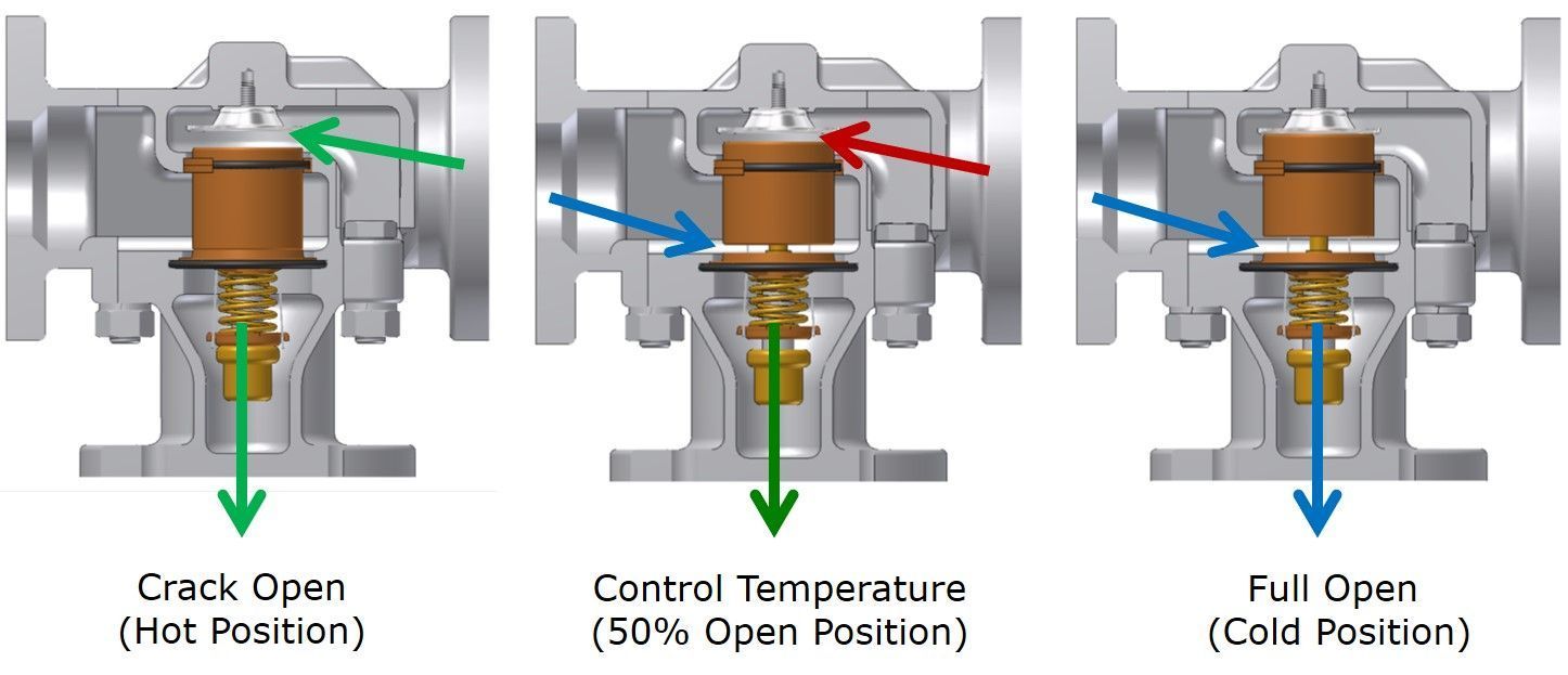
Figure 27A: A diagram demonstrating the position adjustment of the thermal element in a 3-way thermostatic valve.
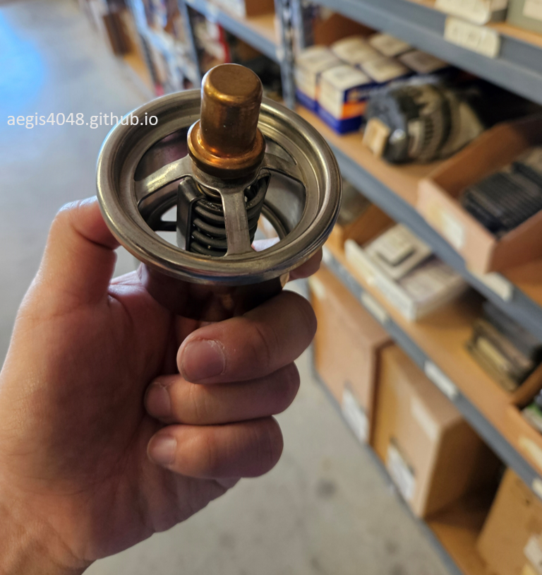
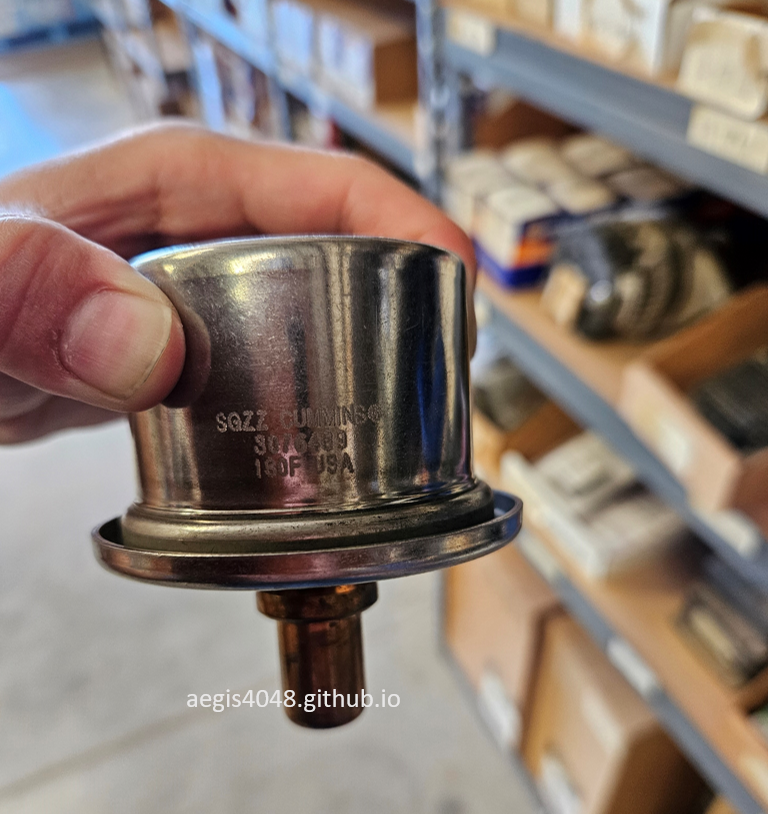
Figure 27B: Thermal element set at 180°F. These are to service older compressor models designed for lower operating temperatures. Typical Flogistix thermostat valves 210-230°F thermal elements.
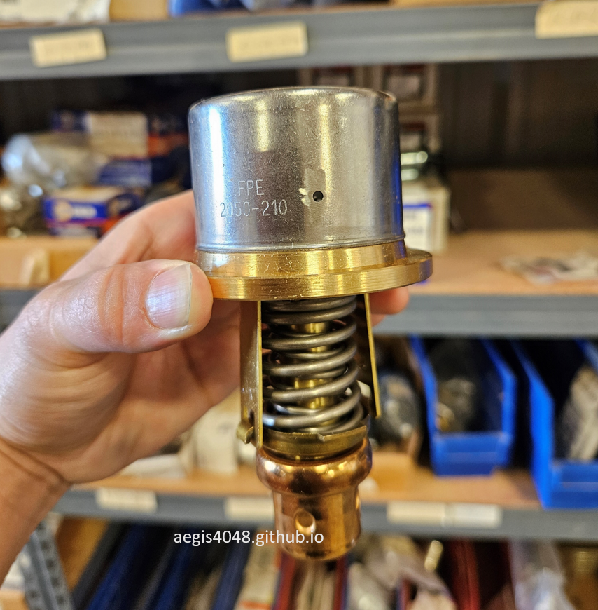
Figure 27C: A thermal element with 210°F setpoint .

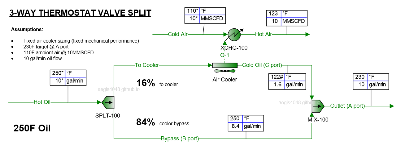
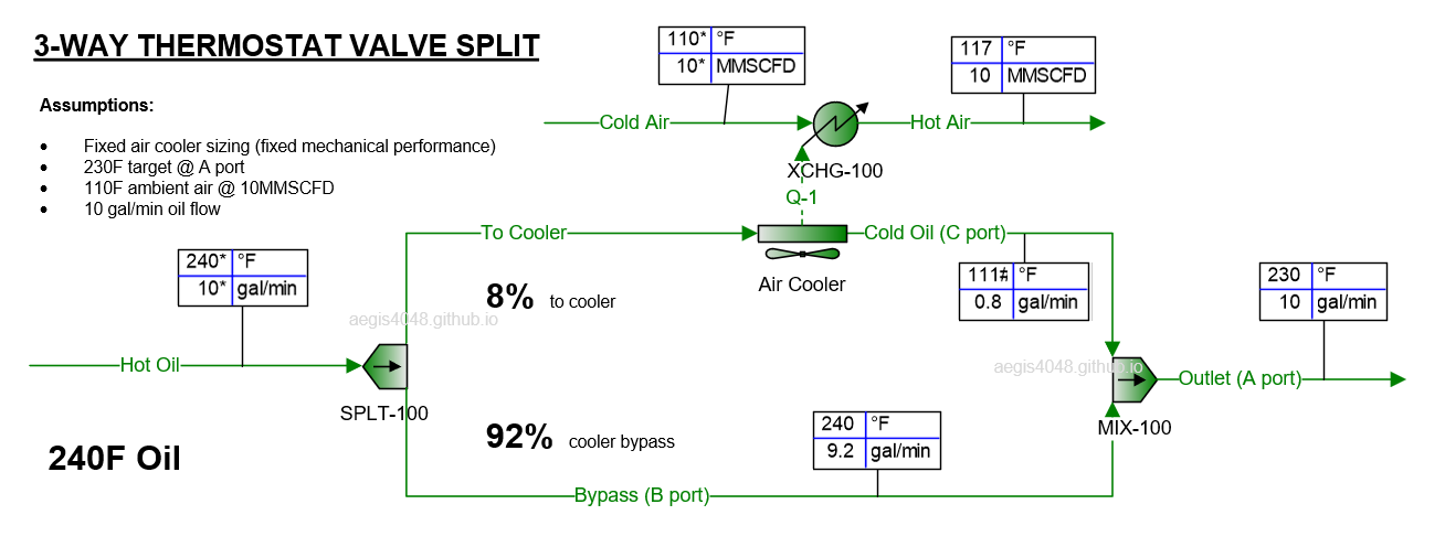
Slideshow 4: Simulation of 3-way thermostatic valve operation set at 230°F with varying inlet oil temperatures, demonstrating oil flow splits between the cooler bypass (hot, B-port) and cooler path (cold, C-port) to maintain target outlet temperature at A-port. The simulation assumes constant cooler performance with fixed sizing (configuration not shown). The valve's internal thermal element (typically an expanding thermocouple) automatically adjusts the hot/cold mixing ratio through real-time temperature response, with the simulation calculating the exact split ratios required to achieve the 230°F setpoint.
The role of the 3-way thermostat valve differs between electric and gas engine compressor models. While detailed temperature control operations for both models are discussed in Section 9, the following provides a quick overview of the functional differences between model types:
-
Electric
Electric compressors have a dedicated motor driver for the cooling fan. The motor receives a control signal from the PLC to adjust fan RPM based on lube oil temperature feedback. Fan RPM adjustment provides the primary temperature control. The thermostat valve serves as a secondary backup, preventing high-temperature spikes if the fan cannot react quickly enough to sudden load changes. Refer to Section 9.1 for details on electric model temperature control.
-
Gas Engine
Gas engine compressors have only one driver—the engine crankshaft—which extends to both sides: one side drives the compressor rotors, and the other side drives the cooling fan through a belt-pulley assembly. The PLC prioritizes RPM control for the rotors, causing the cooling fan RPM to float. Real-time fan speed control is not possible. The thermostat valve acts as the sole real-time temperature control. However, the valve cannot maintain the target temperature if the fan cannot remove sufficient heat, especially during recycle mode (see Section 8.3) when both compressor and fan RPM decrease, reducing cooling capacity. Refer to Section 9.2 for gas engine temperature control details.
Electric models benefit from having two temperature control mechanisms: fan RPM adjustment as the primary control, and the thermostat valve as the secondary control. Gas engine models rely solely on the thermostat valve. This fundamental difference makes electric models superior in cooling performance compared to gas engine models.
7.5. Liquid level switches
Unlike pressure or temperature transmitters (typically under $1,000), continuous level transmitters are significantly more expensive ($2,000-$6,000). As a cost-effective alternative, many systems use simple float switches instead of continuous monitoring devices. These switches employ a floating element to detect when liquid levels reach predetermined setpoints, triggering dump valve signals, alarms, or shutdowns without providing constant level data. Continuous monitoring type level gauge transmitters are usually used for storage tanks, while float switches are used for separators and scrubbers.
Liquid level switches have a floating element that detects liquid level rise and fall inside a vessel. The floating element density is lighter than the liquid. The floating element connects to the bolted body through a thin rod that triggers the switch depending on the position of the floating element. Level switches can be pneumatic type or electric type. When liquid level reaches setpoint levels, the switch connects/disconnects the electric circuit or allows/cuts off pneumatic supply.
For oil-flooded screw compressors, these level switch signals are shown in Figure 17: suction scrubber high level shutdown (LSHH-1000), discharge scrubber low level shutdown (LSLL-3000), and blowcase liquid dump (LS-1010).
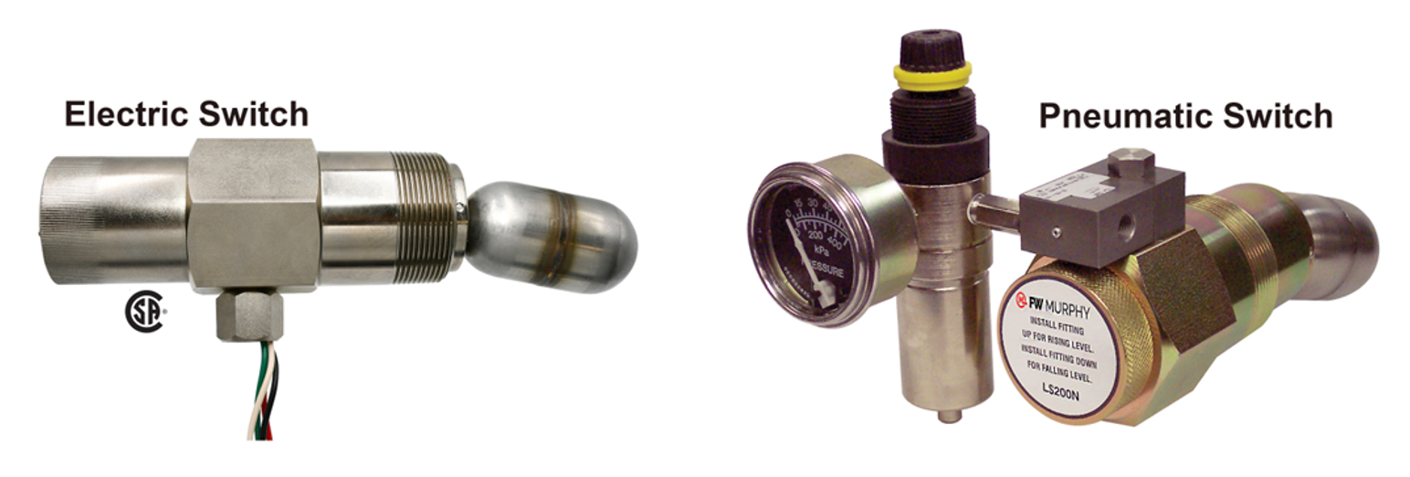
Figure 28: Murphy LS200 (left, eletric) and LS200NDVOR (right, pneumatic, w/ pressure regulator) liquid level switches. Image adpated from: FW Murphy
7.5.1. 3-Way pneumatic type
Liquid level switches operate on identical principles to 3-way solenoid valves (Section 7.3), with one key distinction: instead of receiving electrical signals from a control system, the pneumatic switches are actuated by a floating element that detects liquid levels at a predetermined height. Both devices feature the same three-port configuration (inlet, outlet, vent) and share the same emission issues when vented to atmosphere without a closed capture system and when air compressors are unavailable.
Pneumatic liquid level switches control the passage of pneumatic supply based on a predefined level setpoint. The setpoint is usually the install height of the switch. They are used for periodic liquid dumping, emergency shutdowns, and alarms. Slideshow 5 demonstrates the working mechanism of a pneumatic level switch paired with a dump valve for vessel liquid removal.
This provides a detailed view of the blowcase (V-101), level switch (LS-1010), and dump valve (CV-1011) operations, which were also shown in Slideshow 2. The key difference is that Slideshow 2 splits the pneumatic supply downstream of the level switch into three lines to simultaneously control three valves (CV-1001, CV-1010, and CV-1011), while Slideshow 5 simplifies the demonstration by showing only one pneumatic line for one dump valve.
Figure 29 illustrates a Murphy LS200NDVO level switch installed on an oil-flooded screw compressor's suction scrubber. The black rectangular component atop the switch is its pneumatic adapter (Dump Valve Operator, DVO), which directs pneumatic flow based on the floating element's position. This installation features an emission-conscious design with tubing routing vent gas to a closed capture system - a newer configuration responding to increasing environmental concerns about pneumatic gas venting. Most field installations lack this vent capture capability.
In contrast, Figure 31 demonstrates conventional atmospheric venting, evident by the missing third tubing on the pneumatic adapter. However, this particular installation uses compressed air (rather than natural gas) for pneumatic supply, making atmospheric venting environmentally acceptable.
Liquid Level Switch Operation Sequence
- Standby State: Liquid level is low (switch inactive). Supply [IN] port remains blocked while Vent [EXH] port stays open (disconnected from Supply [IN]).
- Level Rise: Liquid reaches activation height, triggering the switch.
- Supply Activation: Switch opens Supply [IN] to Supply [OUT] flow path while closing Vent [EXH].
- Diaphragm Activation: Pneumatic pressure lifts the dump valve diaphragm.
- Dump Phase: Valve fully opens, releasing accumulated liquid.
- Level Drop: Liquid falls below setpoint, triggering switch reset.
- Supply Cutoff: Switch closes Supply [IN] and reopens Vent [EXH].
- Pressure Venting: Residual diaphragm pressure exhausts through Vent [EXH].
- Emission Control: Venting occurs either to atmosphere (Figure 31) or closed capture system (Figure 29).
- System Reset: Dump valve fully closes, completing the cycle.
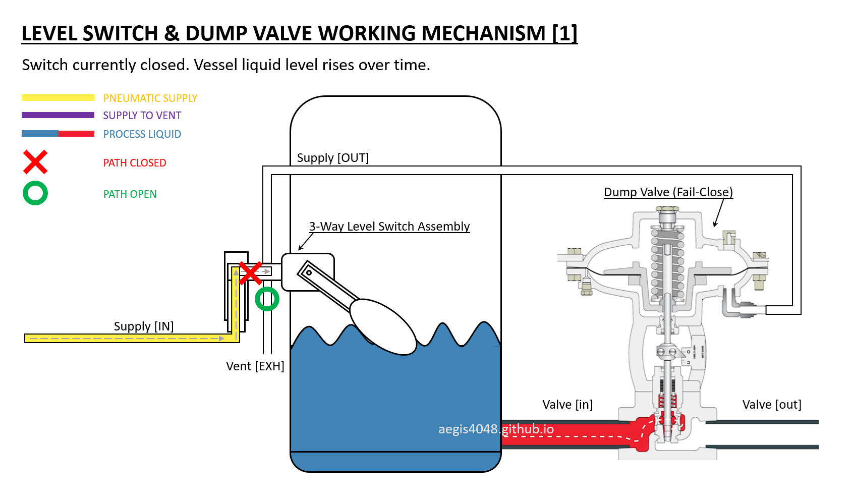
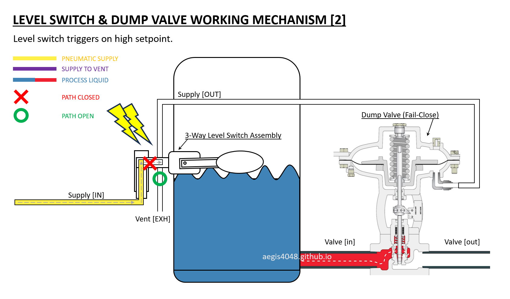
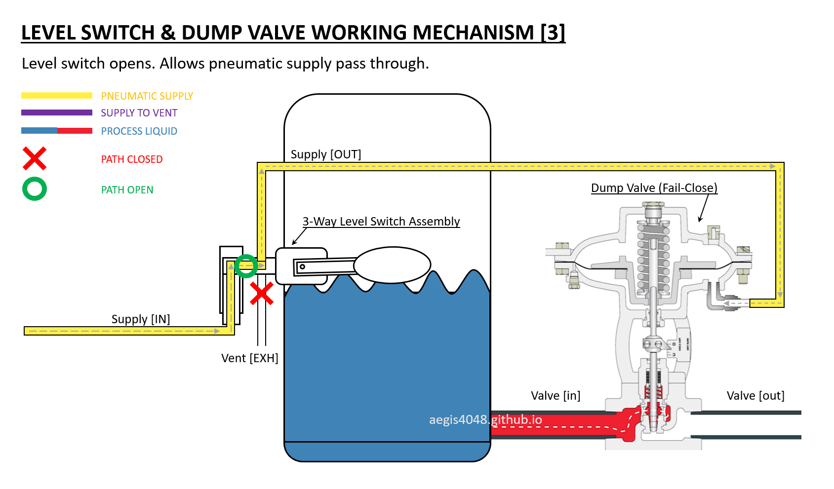
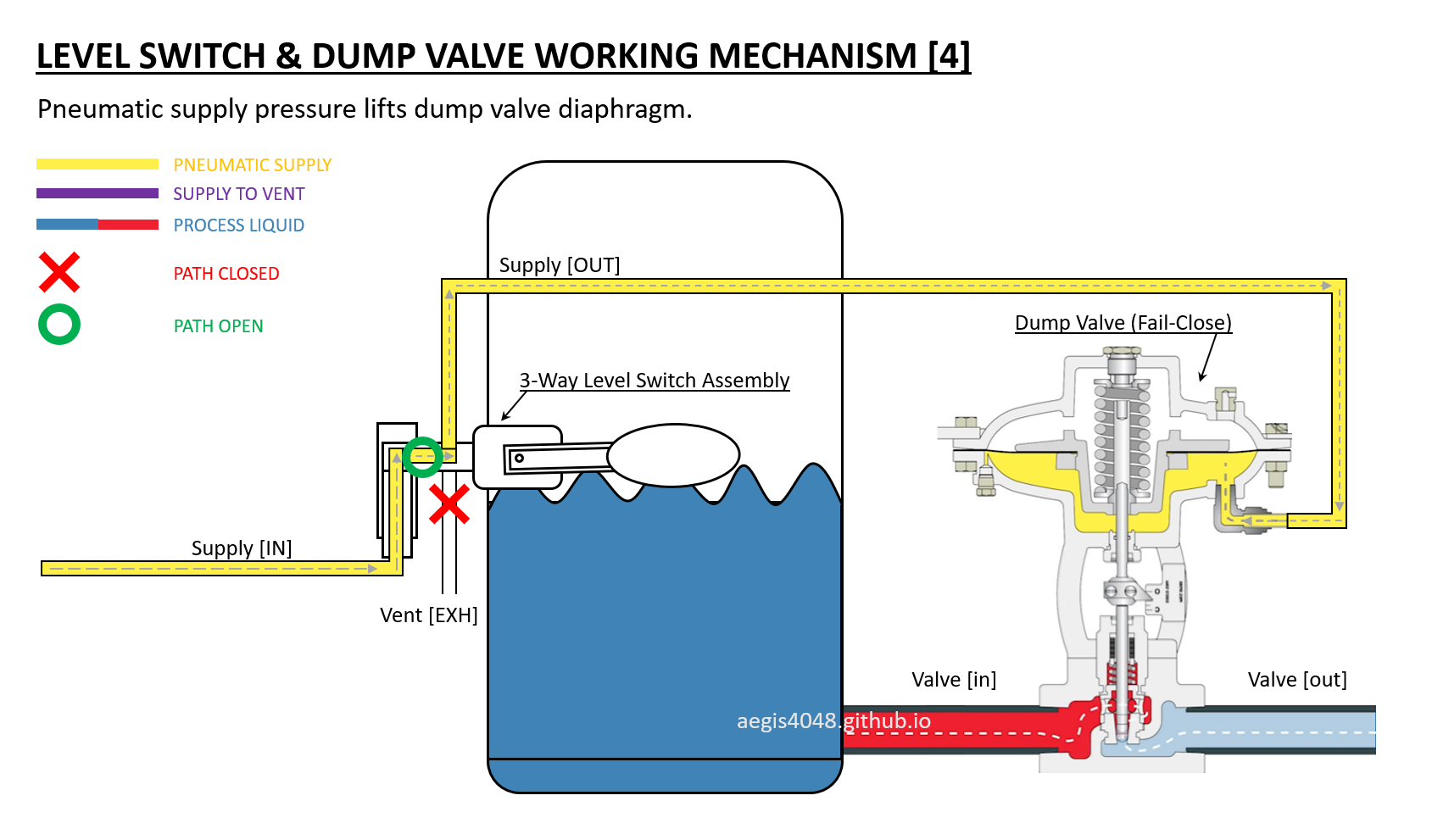
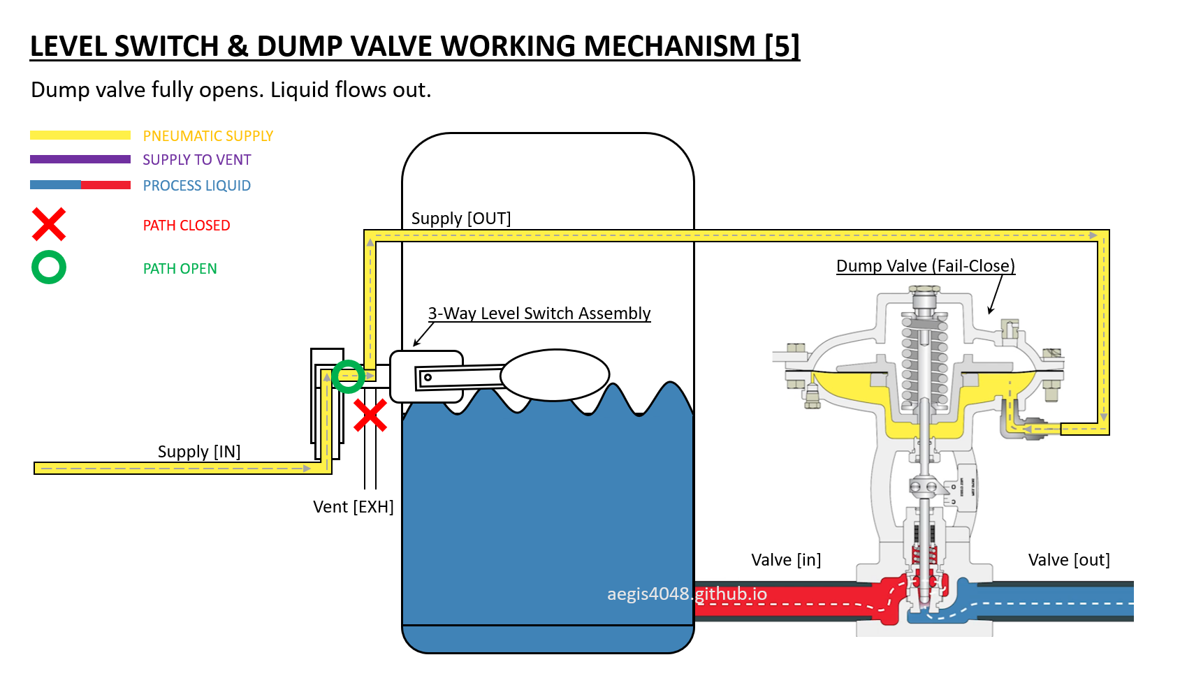
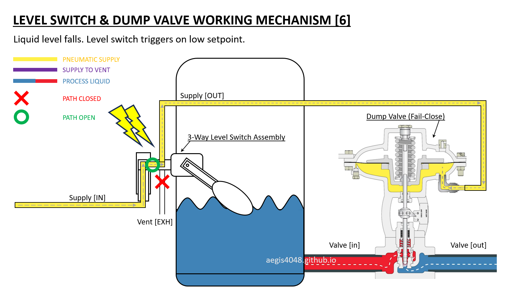
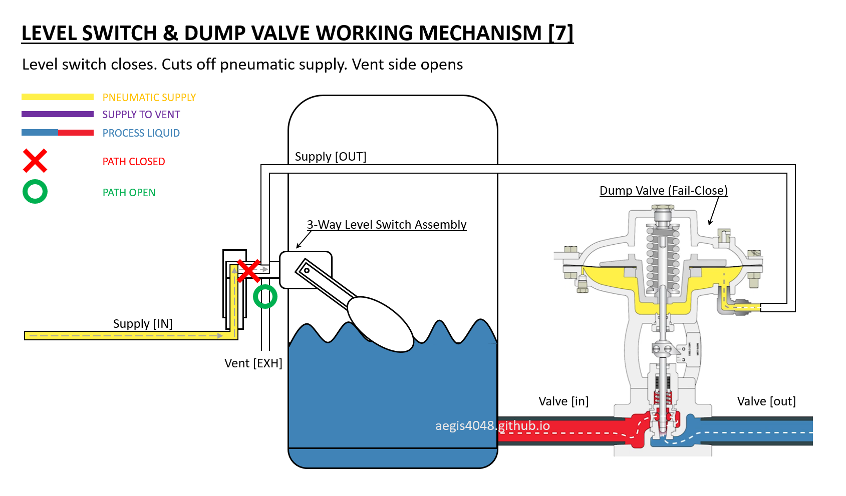
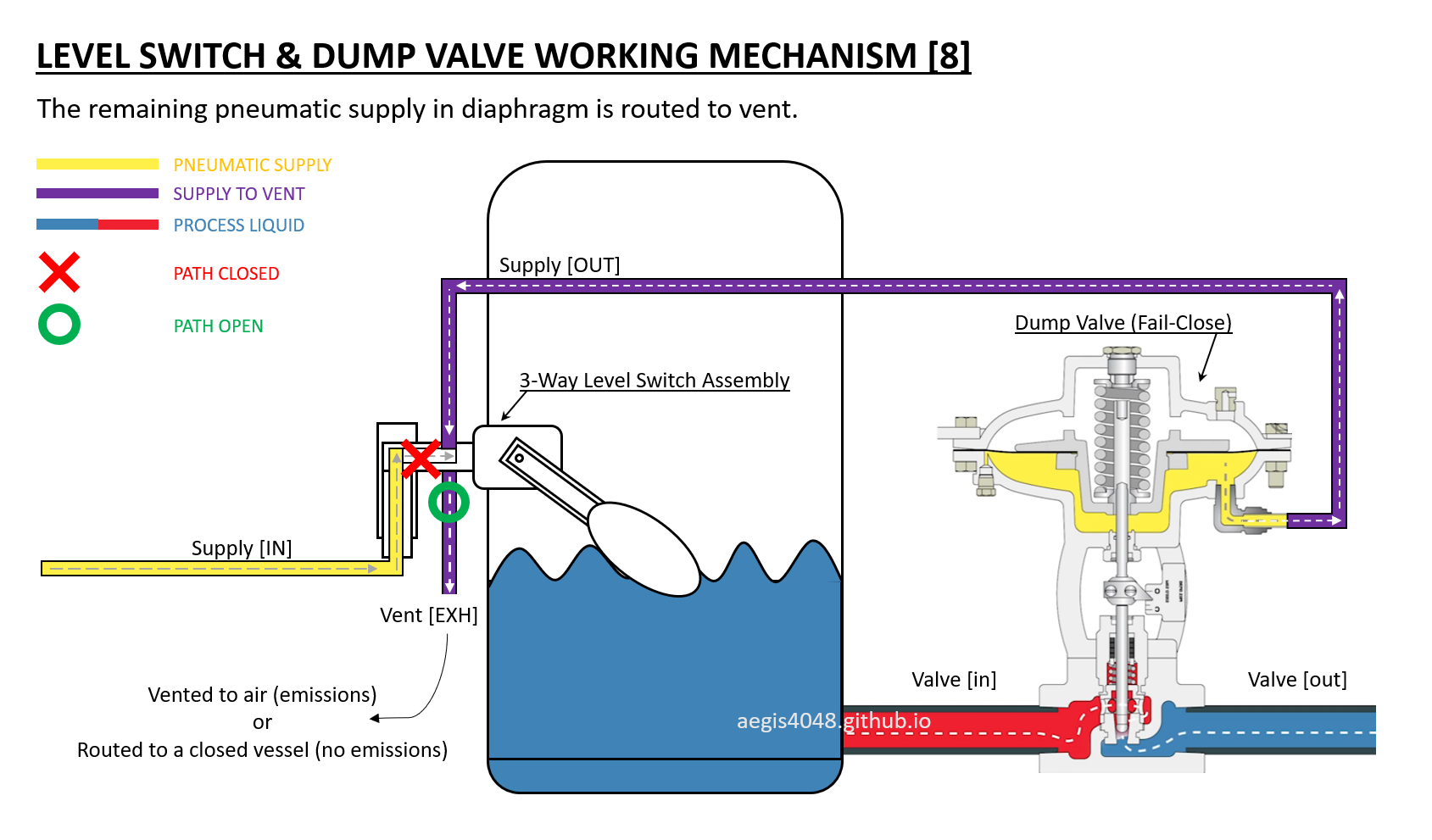
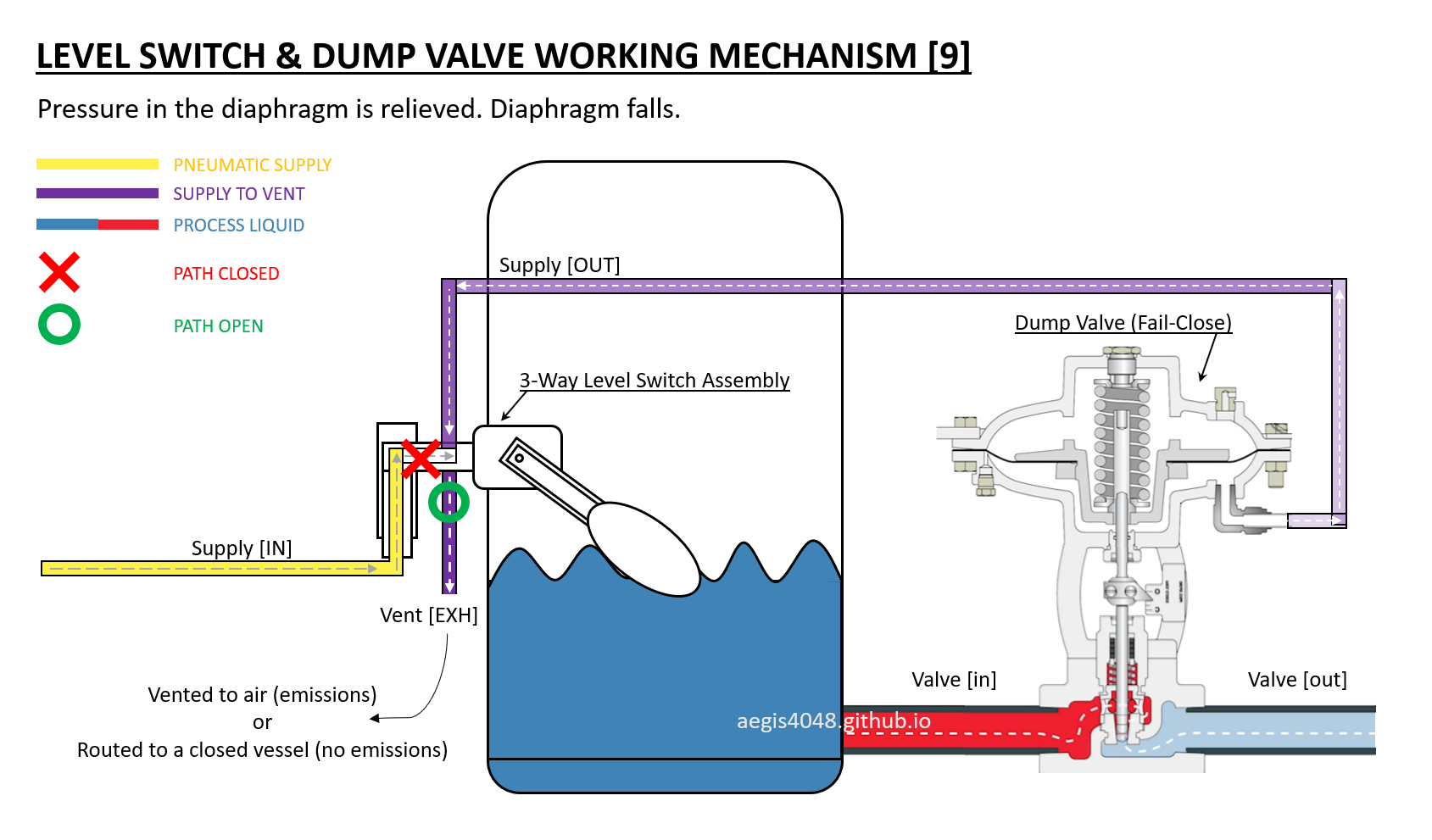

Slideshow 5: Demonstrates operation of a liquid level switch with fail-close dump valve. When liquid exceeds the setpoint (determined by switch installation height), the switch activates and permits pneumatic supply (15-30 psig natural gas or air) to flow. This pressure acts on a diaphragm containing a 10-15 psig spring (set below pneumatic supply operating pressure), forcing it upward to open the dump valve. When level drops, the switch deactivates to cut supply pressure while venting residual pressure through the vent port, allowing the spring to return the diaphragm to its fail-safe closed position. Valve diagram adapted from: Kimary video.
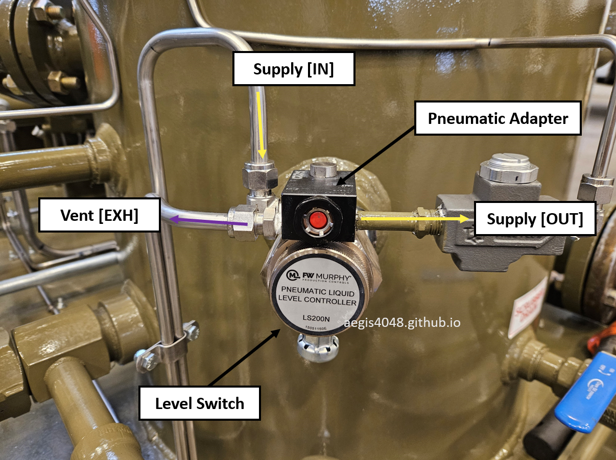
Figure 29: Pneumatic liquid level switch installation on an oil-flooded screw compressor suction scrubber for liquid dump control. This specific model is a Murphy LS200NDVO pneumatic level switch. The wall-mounted switch (via NPT connection) features a pneumatic adapter that receives mechanical signals from its floating element, functioning as a flow director. This compressor application benefits from easier vent routing to a closed capture system since the entire assembly is self-contained on a compact skid. In contrast, field installations for separator dump valves rarely use closed capture systems due to the greater complexity and difficulty of running vent tubing across larger field installations.
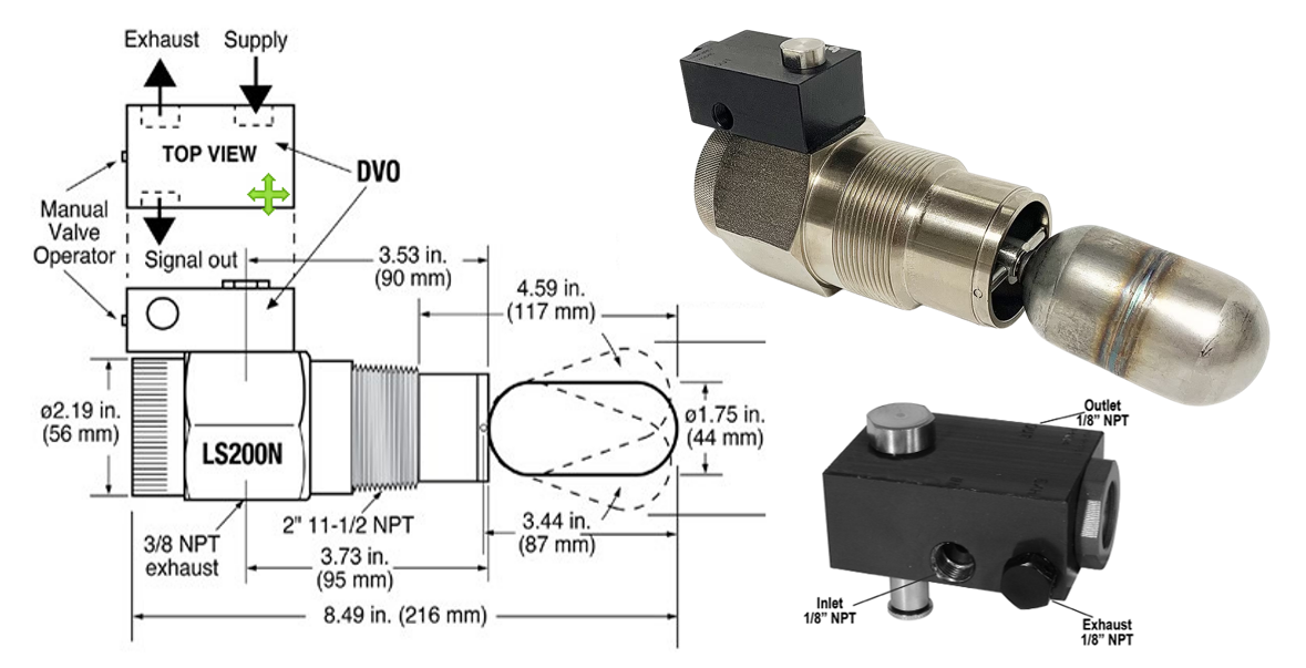
Figure 30: More detailed look at the Murphy LS200NDVO liquid level switch shown in Figure 29. The black rectangle mounted on top of the silver switch body is the pneumatic adapter. The manufacturer designates this adapter as a "Dump Valve Operator (DVO)." Image adapted from: FW Murphy
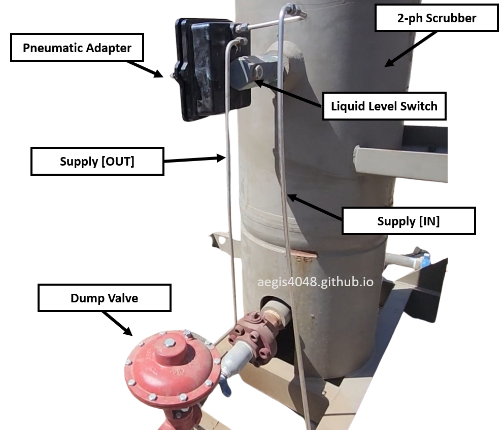
Figure 31: Field installation of a 2-phase suction scrubber, level switch, and dump valve serving a 3-stage reciprocating compressor. The pneumatic adapter's configuration - missing the third tubing - confirms atmospheric venting of the pneumatic supply for the level switch. This installation utilizes compressed air (rather than natural gas) as the pneumatic medium, making the atmospheric venting environmentally acceptable since only clean air is exhausted. Note that the level switch used in this photo is not Murphy LS200.
7.5.2. Electric type
Electric liquid level switches are much simpler than pneumatic types. When levels rise/fall to a setpoint, the internal electric circuits connect and allow current to flow. When the switch is off, there's constant current supply into the switch, but no flow out due to disconnected circuits. When circuits connect, current flows to a control panel as a signal. Electric switches aren't normally used for dump valves, but mostly for abnormal/safety situation alarms/shutdowns to a control panel, or to activate electric pumps.
Figure 32 shows Murphy LS200 electric level switch, and Figure 33 shows the electric switch installation on discharge scrubber for low lube oil liquid level kill, and on suction scrubber for high knock out liquid level kill.
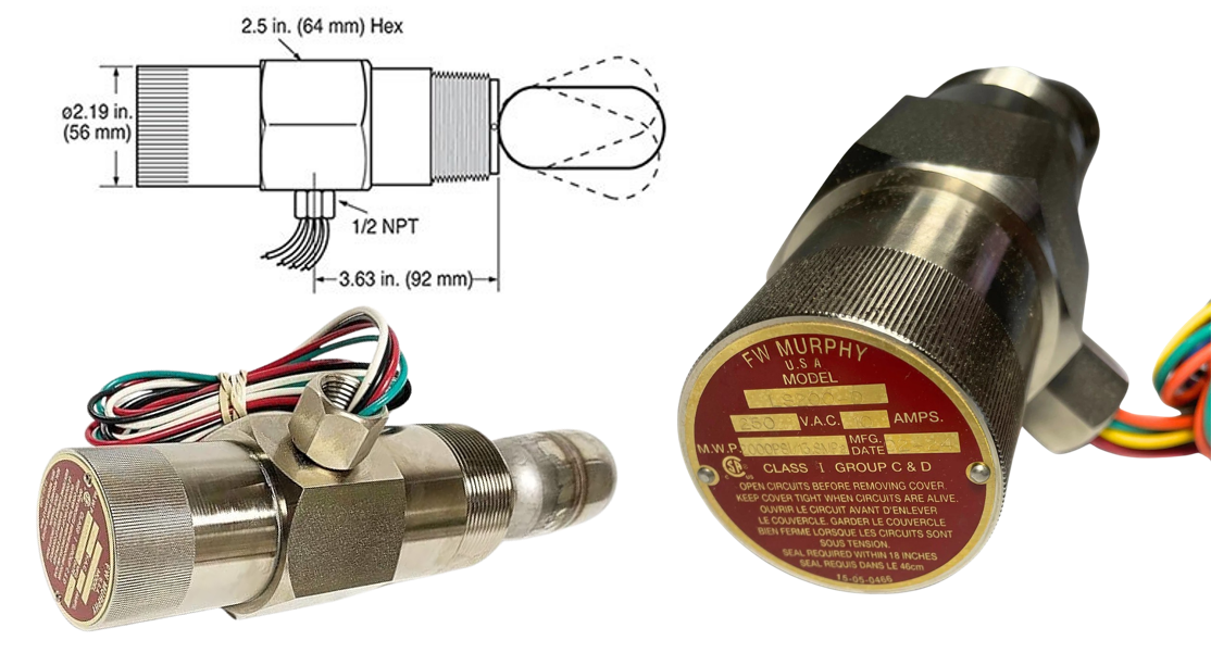
Figure 32: Product illustration of Murphy LS200 electric liquid level switch.
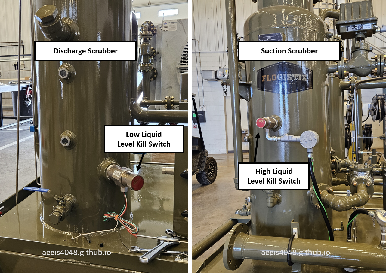
Figure 33: Shows level switch installations on an oil-flooded screw compressor. Left: Low lube oil level kill switch for discharge scrubber (wiring incomplete, captured during manufacturing). Right: High liquid level kill switch for suction scrubber (wiring complete, connected to PLC via junction box). The vertical positioning difference between switches demonstrates how setpoints are determined by installation height - the high-level switch mounts higher than the low-level switch.
7.6. Electric liquid pump
Fully electric compressor models that use an electric pump for suction scrubber liquid dumping (instead of the integrated blowcase system described in Section 6) utilize two electric liquid level switches for pump control: a middle switch that sends the turn-on signal to the pump when liquid reaches the upper level, and a bottom switch that sends the turn-off signal when liquid falls to the lower level, as shown in Figure 34 where these switches correspond to the middle (pump on) and bottom (pump off) positions.
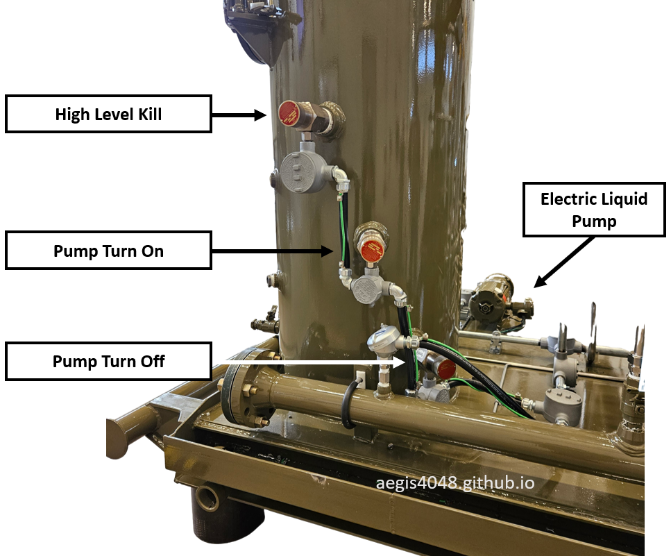
Figure 34: Electric liquid pump used in conjunction with suction scrubber's two electric level switches (Murphy LS200) for pump turn on/off signals.
Video 1: Simple demonstration of a float switch-activated electric pump.
7.7. Pressure safety valves
Most compressors use spring-loaded pressure safety valves (PSVs) for overpressure protection. As shown in Figure 35, these PSVs feature a 90° angled body design with an outlet diameter larger than the inlet to prevent flow choking. The setpoint pressure is always determined by the MAWP (Maximum Allowable Working Pressure) of the system's weakest component. For example, in a system where the discharge scrubber and flanges are rated for 500 psig but the Leroi HG series compressor has an MAWP of 350 psig, the discharge scrubber PSV would be set at 350 psig to protect the compressor. Following API 520 standards, the PSV begins simmering at the setpoint (350 psig), fully opens at 110% MAWP (385 psig) for normal overpressure scenarios. While 121% MAWP is used for fire case, compressor PSVs aren't sized for fire cases.
Oil-flooded screw compressors require three separate PSVs (Figure 36) due to different pressure ratings: one for the discharge scrubber (set at compressor MAWP), one for the suction scrubber, and one for the integrated blowcase which operates at different pressures than the suction scrubber. When activated, PSVs provide rapid, abrupt pressure relief through their 90° upward piping - a critical safety feature demonstrated in Figure 37, where lube oil from a discharge scrubber reservoir was propelled to the ceiling during final quality testing at the manufacturing facility. The 90° upward piping prevented potential injury to test loop operators by ensuring the 385 psig (350 psig MAWP + 10% overpressure) discharge was directed vertically rather than horizontally (Figure 38 shows horizontal pressure relief without the 90° upward piping). This incident occurred during performance test loop operation when system pressure exceeded the PSV's 110% overpressure setpoint. While the PLC typically initiates shutdown at the 350 psig setpoint pressure, the PSV remains the ultimate safety barrier when other controls fail.
Unlike field separators that may route relief to closed systems or flares, compressor packages from third-party vendors typically vent directly to atmosphere. This design approach stems from operational flexibility requirements: (1) compressors may be installed either before production begins or added later during field development, and (2) they can be removed from service at any time based on production rates and economic factors. These installation and release cycles make dedicated flare headers for compressor PSVs impractical, necessitating atmospheric venting with the standard 90° upward discharge piping for safe operation.
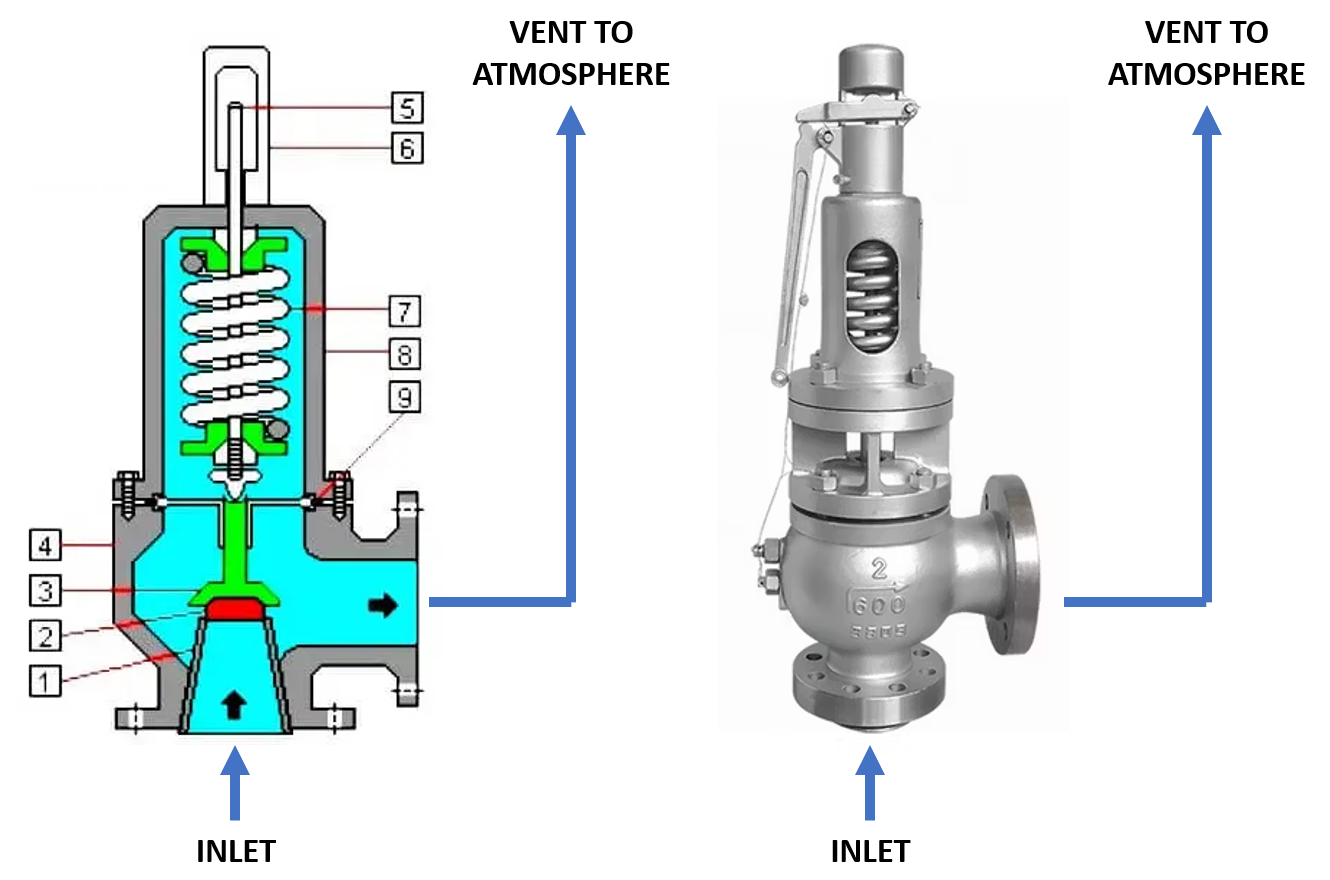
Figure 35: Spring-loaded pressure safety valve (PSV) illustration. Blue arrows indicate atmospheric relief piping. The relief side may vent directly to atmosphere or connect to a flare header for combustion.
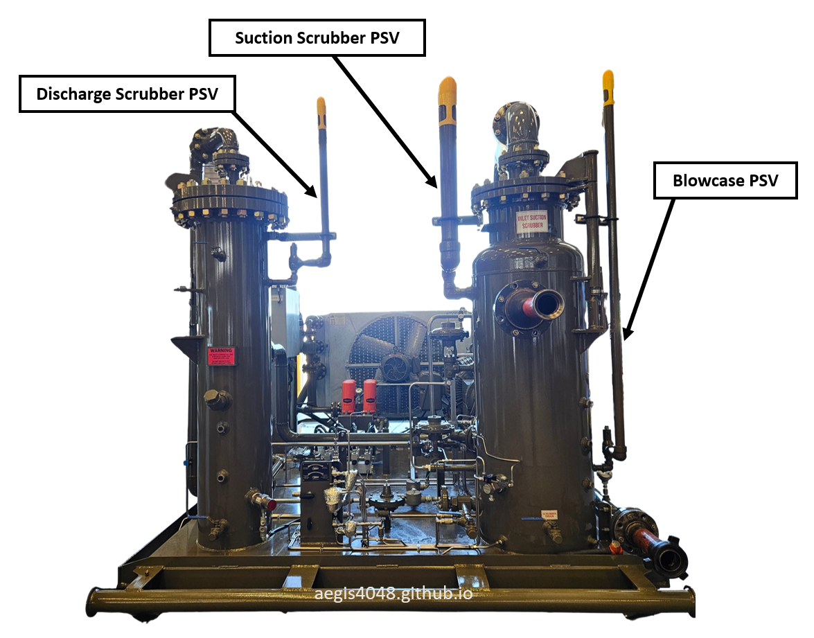
Figure 36: Three PSVs on an oil-flooded screw compressor for: (1) discharge scrubber (left bottle), (2) suction scrubber (right bottle), and (3) integrated blowcase. The blowcase (inside the suction scrubber) operates at different pressures than the suction scrubber, requiring its own PSV. See Section 6 for blowcase details.
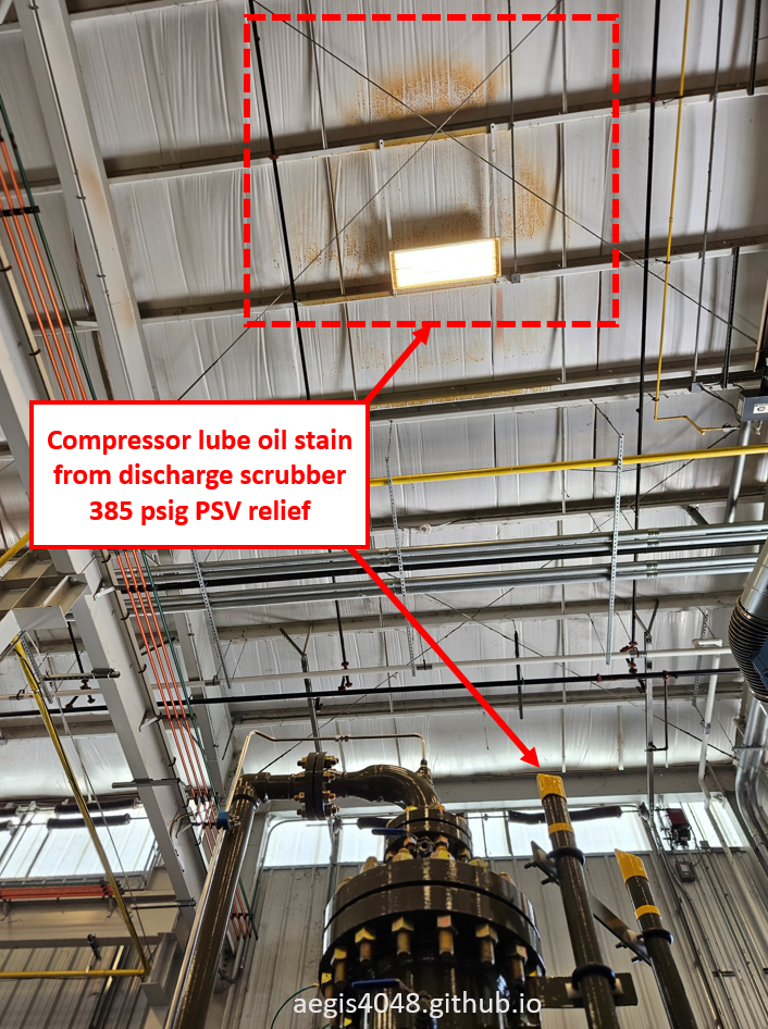
Figure 37: Lube oil stain on the manufacturing facility ceiling caused by discharge scrubber PSV activation during final quality testing. This specific spot inside the building marks the compressor test loop area where units undergo pressurized testing before shipment. During one such test, system pressure exceeded the PSV setpoint of 385 psig, causing the valve to open violently. The sudden release propelled lube oil from the ground-level discharge scrubber reservoir with enough force to reach the ceiling height, leaving this visible stain as evidence of the pressure magnitude.
Figure 38: PSV activation demonstration showing sudden pressure burst. Atmospheric vent PSVs require upward 90° piping to direct bursts safely away from personnel. GIF adapted from: Youtube Shorts
7.8. Transmitters
Various transmitters send process condition feedback signals to the PLC to control a compressor unit. This section summarizes some of the key transmitters used to control oil-flooded screw compressor operation. See Section 8: Pressure control and Section 9: Temperature control to see how these transmitter feedbacks are used. Note that the number and type of transmitters may vary depending on the packager and model. PT stands for pressure transmitter. TT stands for temperature transmitter.
Suction PT: Installed either on the suction scrubber, or on the suction scrubber's gas outlet line. Pressure readings on the suction PT are assumed to represent the pressure of the source vessel. PLC sends RPM ramp up/down signal to a driver based on this feedback.
Source Vessel PT: (optional) Installed directly on top of a source vessel and wired to the compressor PLC. Used for low suction pressure applications like tank vapor recovery operating in ounces. Compressor inlet readings may show falsely low pressures due to friction loss. Not needed for applications operating in psig. Can also be used for applications in which the source vessel pressure must operate higher than the maximum allowable pressure of a compressor suction, such as ESP casing drawdown.
Discharge PT: Sends discharge pressure feedback to the PLC. Triggers high discharge pressure shutdown when salesline sees abnormally high pressure beyond compressor MAWP due to process upsets.
Suction TT: (optional) Helps identify potential dew point issues. Higher suction temperature increases water vapor saturation, which raises the dew point temperature (see Section 10.5).
Lube Oil Injection TT: Monitors lube oil temperature on the injection side. Temperature must stay below the thermostat valve setpoint (see Section 7.4) to avoid high-temperature shutdown. Temperature exceeding the valve setpoint indicates either the thermostat valve or cooler failure.
Discharge TT: Installed at the 2-phase outlet of the compression chamber. Tracks post-compression temperature increase. Healthy trend should read 5–15°F higher than the lube oil injection temperature, as shown in Figure 58. 0-5°F gain in temperature indicates insufficient compression volumes, or an oversized unit.
Lube Oil Injection PT: Monitors lube oil pressure on the injection side. Leroi manual specifies injection pressure to be 60–100 psig above suction pressure. Low readings may indicate a failed or miscalibrated back pressure valve (e.g., BPV-3000 in Figure 15).
Post-Cooler Gas TT: (optional) Measures final discharge gas temperature after the cooler. Electric models may use this signal to control fan RPM. Most electric units target lube oil temperature instead so this is optional. Has no use on engine models since fan RPM is can't be independently controlled.
Engine Manifold PT: Measures intake manifold pressure—the pressure of the air-fuel mixture entering the engine cylinders. This is a critical input for the Air-Fuel Ratio Controller (AFRC). See Section 8.2 for more details.
Engine Oil PT: Monitors engine oil injection pressure. Like lube oil used for the compression chamber, the engine requires a minimum specified pressure for proper lubrication. This PT can triggers low engine oil pressure shutdown of oil pressure drops too much.
Engine Coolant TT: Provides temperature feedback for the coolant loop that cools the engine block and prevents overheating. Not that this transmitter can only trigger shutdown, and can't control fan RPM for the coolant.
MPU: Magnetic Pickup Unit monitors engine RPM. The RPM signal is sent to the PLC, which adjusts the governor and AFRC to control fuel and air ratio accordingly. Example shown in Figure 44.A.
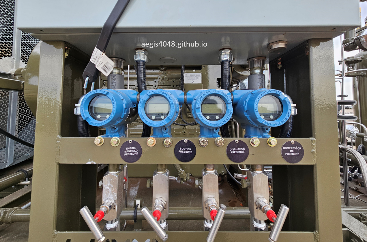
Figure 39: Pressure indicating transmitters on a gas-engine oil-flooded screw compressor package. Additional pressure and temperature transmitters (not shown) provide PLC operational control. The silver needle valves feature a dual-handle design: the lower (front) handle for pressure isolation while the upper (rear) handle for pressure vent after isolation.
7.9. Suction control valve
A suction control valve (SCV) is a type of a pressure-reducing regulator that maintains outlet pressure at a target setpoint. It is not part of a compressor skid package, but installed outside a skid on the inlet piping into a suction scrubber. It serves two critical purposes: (1) ensuring pressure stays below a desired setpoint to prevent high suction pressure shutdown, and (2) maintaining pressure sufficiently close to setpoint to preserve desired flowrate capacity. As shown in Table 1 of Section 1.4, increasing suction pressure boosts flowrate capacity but also increases horsepower demand. The SCV must carefully balance these competing factors - excessive pressure risks high-HP shutdowns, while insufficient pressure reduces capacity and may force gas flaring to relieve excess gas. All compressors have a manufacturer-specified maximum suction pressure; exceeding this limit will make the compressor to run out of horsepower and cause a shutdown.
The SCV maintains pressure through purely mechanical operation of its pressure pilot system (best explained in Video 2 by Kimray, HIGHLY recommend you to watch it). The process works as follows (see Figure 42 and 42A for example illustrations):
SCV Working Principle
- Process pressure acts on the pilot diaphragm through the sensing line.
- Diaphragm movement by the sensing line pressure physically adjusts the pilot plug. The position of the plug determines supply pressure passthrough or cutoff.
- If pass through, the pilot plug lifts to let supply pressure flow into the diaphragm chamber of the main control valve.
- If cutoff, the pilot plug falls to cutoff supply pressure. The remaining pressure in the main control valve's diaphragm chamber is vented through the pilot's vent port.
- The diaphragm movement of the main control valve positions the control valve plug, allowing process gas passthrough or cutoff.
When the sensing line pressure rises above setpoint, the pilot diaphragm moves to cutoff supply gas, closing the control valve. When pressure drops below setpoint, the diaphragm opens to allow supply gas passthrough, opening the control valve. This mechanical balance continues until stable pressure is achieved. Figure 40 shows a real-life SCV installation on a heater treater vapor recovery for stable suction pressure control.
It's important to note that during supply gas cut off, the mounted pilot vents the supply pressure through the vent port (shown in Figure 42A), which is a source of emission when gas is used instead of air.
SCVs are not installed on tank (below 1 psig) or VRT (1-5 psig) vapor recovery applications because these vessels will never generate sufficient suction pressure to trigger high-HP compressor shutdowns. For separator and heater treater applications, SCVs (costing $1,500-$2,500 per valve package) are only installed when pressure swings could substantially affect compressor operation. They are mandatory for wellhead-proximate applications like casing or primary separator drawdown applications, where 200-300% pressure fluctuations frequently occur. Downstream vessels with stable operation may not require SCVs depending on their pressure characteristics.
Sensing Line: Monitors process pressure (typically from inlet manifold or suction scrubber) and provides pressure feedback to the pilot.
Supply Line: Delivers pneumatic supply (10-45 psig instrument gas/air) to actuate the control valve diaphragm.
Pressure Pilot: Processes sensing line feedback to allow/cutoff supply pressure to the diaphragm, featuring a vent port that can be a source of emissions.
Control Valve: Main gas flow path regulated by diaphragm position from pilot signals.
Optional accessories may include drip pots, filters, or regulators depending on application requirements.
Video 2: Illustration of a suction control valve, which is a type of a fail-close pressure-reducing regulator, by Kimray.
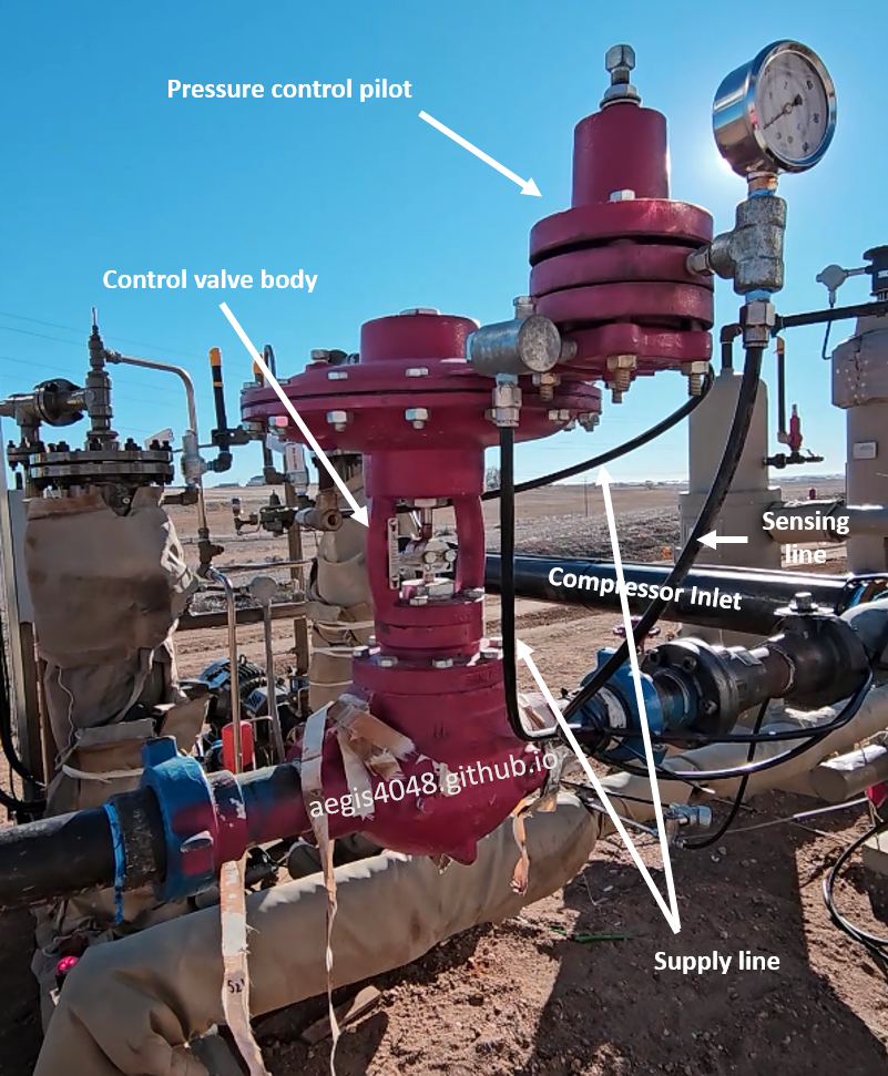
Figure 40: Fail-close SCV installation on oil-flooded screw compressor for heated separator vapor recovery (30 psig setpoint). The spring-adjustable pilot maintains suction scrubber pressure, preventing high HP shutdown maintaining enough pressure to ensure desired flow capacity.
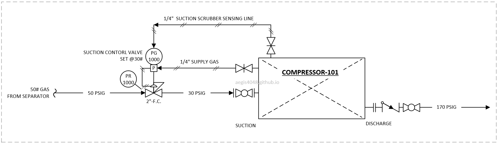
Figure 41: P&ID of a fail-close SCV installation shown in Figure 40.
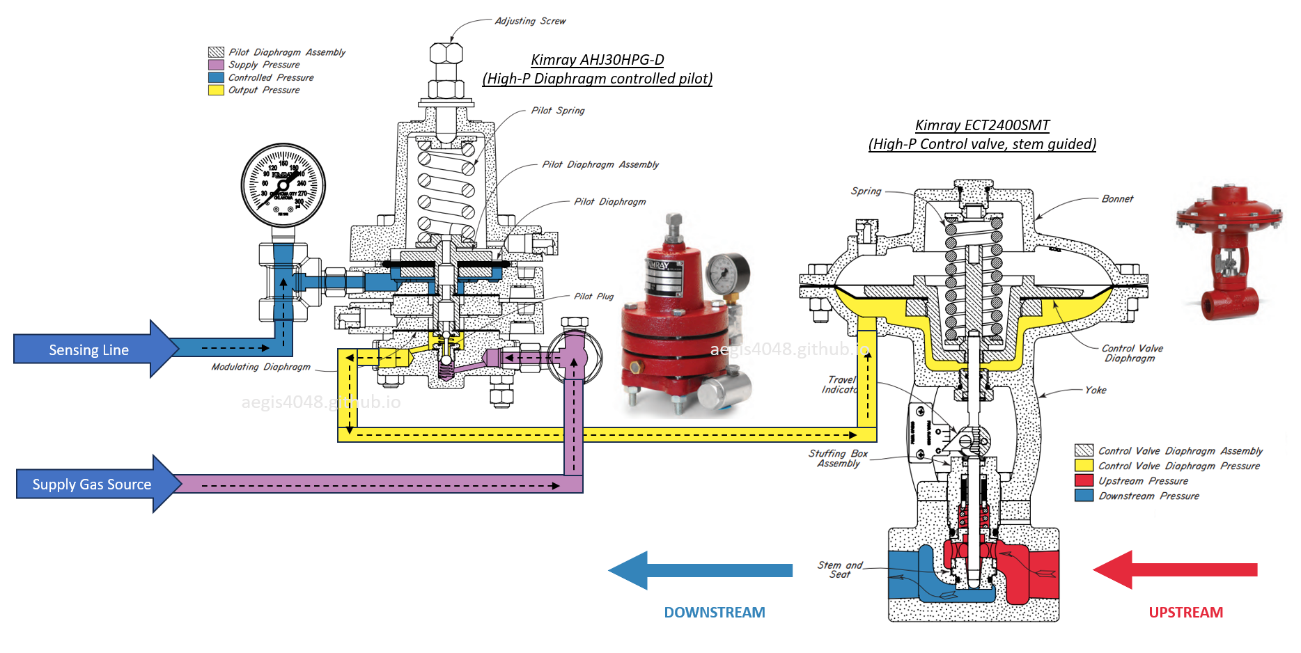
Figure 42: More detailed illustration of a fail-close SCV installation shown in Figure 40. Image adapted from: Kimray
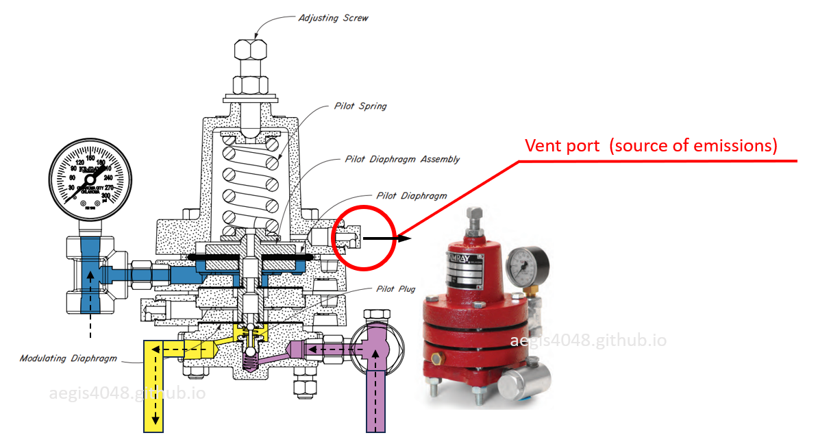
Figure 42A: The sensing line (blue) controls the movement of the pilot diaphragm that controls supply gas pass through or cut off. During supply pressure cutoff operation, the pilot diaphragm moves accordingly to vent supply pressure to the vent port, which is a source of emissions when gas is used operate the pilot instead of air. Image adapted from: Kimray
7.10. Back pressure valve
The back pressure valve (BPV) controls lube oil injection pressure into the compression chamber. Oil-flooded screw compressors require sufficient injection pressure to ensure proper lubrication, cooling, and sealing of the rotors. For instance, the Leroi compressor manual specifies that lube oil injection pressure must be 60–100 psig higher than suction pressure. If suction is 0 psig, injection pressure must be at least 60 psig. If suction reaches the maximum of 50 psig, injection pressure must be at least 110 psig.
In Figure 15, lube oil is sourced from the liquid outlet of the discharge scrubber (V-300). The vessel’s operating pressure governs the available oil injection pressure. That pressure is maintained either by the salesline pressure or by a back pressure valve (BPR-3000) installed on the gas outlet.
When salesline pressure is low (ex: under 60 psig), a BPV is required to ensure 60-100 psig differential pressure for oil injection. If the salesline pressure is already above 110 psig, a BPV may not be necessary, as discharge pressure alone provides adequate injection pressure. This is similar to separator designs where the vessel pressure is either controlled by a BPV or the back pressure from the salesline. Sites with high line pressure often omit the BPV. Those with low pressure must use a BPV to maintain vessel pressure for liquid dump.
While compressors deployed to high line pressure areas technically don’t need BPVs, most units are still built with them. This ensures operational flexibility, since units often get relocated. A compressor might start in a 200 psig line pressure area but later be moved to a 50 psig site. Including a BPV in every unit guarantees consistent lube oil injection pressure regardless of deployment.
The BPV setup may vary depending on the compressor package:
BPV installed inside the skid: See Figure 42B. In the pictured design, the BPV is mounted directly downstream of the discharge scrubber. This configuration makes the unit fully self-contained and independent of customer setup. It standardizes field service training and avoids misconfiguration, as the packager controls the BPV setpoint. The example shown uses a BPV with an external pilot mounted on the valve body.
BPV installed outside the skid: See Figure 42C. The pictured older model lacks a built-in BPV, requiring the customer to install one on the discharge line after the skid. The example shown uses a BPV with an integrated pilot.
While installing the BPV outside the skid is acceptable, the configuration shown in Figure 42C introduces a design flaw: the supply pressure that operates the diaphragm plate comes directly from the process gas line, downstream of the cooler. This is a problem because the cooler typically drops gas temperature by 50–100°F, causing some gas to condense. With no scrubber between the cooler and the BPV, the process stream becomes two-phase. Supplying this wet gas to the pilot mechanism exposes the diaphragm to liquid, increasing the risk of failure and frequent maintenance.
This issue occurs regardless of whether the BPV uses an integrated or external pilot. The key problem is where the supply gas comes from. Even integrated pilots can perform reliably when configured with a clean, dry external supply. In Figure 42C, a better setup would be to use a BPV that operates with an external dry gas supply—such as Kimray's outside-supply BPV if using gas, or high-pressure BPV package if using air to operate the piston diaphragm.
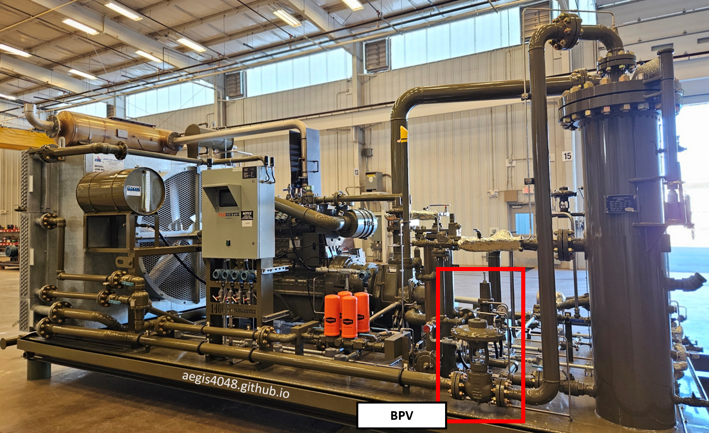
Figure 42B: BPV installed within the skid, directly downstream of the discharge scrubber. This configuration uses an external pilot mounted on the main valve body.
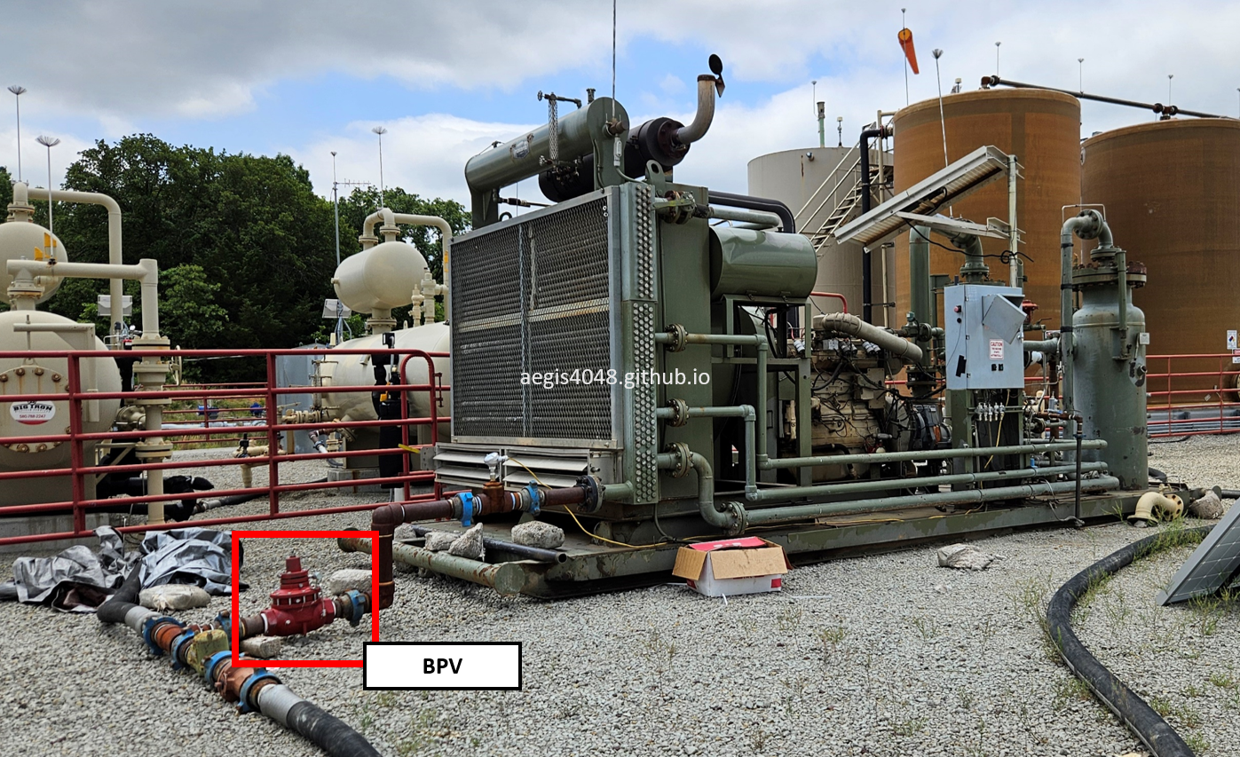
Figure 42C: BPV installed outside the skid, downstream of the cooler. The process stream is two-phase due to condensation across the cooler. Since the valve draws supply gas directly from this wet process stream, the piston diaphragm is more prone to failure. These diaphragms are designed to operate with dry gas or air only.
Note 2: Pneumatic Control Valve Emissions
Many control components on screw compressor skids—such as liquid dump valves, recycle valves, back pressure valves (BPVs), suction control valves (SCVs), solenoid valves, and level switches—can be sources of emissions if they are pneumatic and use instrument gas instead of air. These devices often vent supply gas to atmosphere when actuated, which results in small but continuous emissions.
For example, the liquid dump valve is typically actuated by a 3-way pneumatic level switch that vents gas to atmosphere when closing the valve. Similarly, a pneumatic recycle valve (see Section 7.2) is operated by a solenoid valve (see Section 7.3) that also vents pressure during each cycle. The pilot controllers used on BPVs and SCVs include small vent ports that repeteadly release pressure to air during normal operation (shown in Figure 42A).
These vented gases become emission sources unless captured. This can be mitigated either by using electric control valves—or more practically, by routing the vent lines from pneumatic devices to a closed-capture system. For instance, Figure 29 shows a tubing setup that captures vent gas and routes it to a closed loop contained within a compressor skid, preventing release to atmosphere.
Setting a closed-loop capture tubing systems for a compressor is easier than field-installed separator dump valves, because everything can be contained within a small skid boundary. Check with your compressor vendor what they do to mitigate control valve emissions within their skid.
8. Pressure control
A programmable logic controller (PLC) on a compressor package controls pressure of the source vessel (tank, heater, separator, wellhead, etc). Different applications need different operating pressures - for example, a Vapor Recovery Tower (VRT) requires 2-4 psig. The PLC sends signals to compressor driver to speed up/down, and to a recycle valve to open/close, maintaining source vessel pressure within the target range. These settings are configured at the skid-mounted control panel.
8.1. PID Loop
BEFORE YOU READ: P&ID, with a "&" symbol refers to Piping and Instrumentation Diagram. PID, without the "&" symbol here refers to Pressure-Integral-Derivative.
PLC controls rotational speed of a compressor driver, either electric motor or a gas engine. Pressure transmitters (Section 7.8) on the source vessel or suction line continuously transmit data to the PLC. For VRT applications maintaining 2-4 psig with 3 psig target, if pressure reaches 4 psig (indicating built up gas volumes), the PLC commands higher RPM (e.g., 2000 RPM to 2500 RPM) to draw more gas volumes and reduce pressure. Conversely at 2 psig, it reduces RPM (e.g., to 1200 RPM) or activate recycle mode (Section 8.3) to allow pressure buildup to 3 psig.
The control panel runs a PID (Proportional-Integral-Derivative) loop algorithm that dynamically calculates RPM adjustments. This three-component system: (1) Proportional responds to current pressure deviation (instant RPM change), (2) Integral addresses persistent offsets (gradual correction), and (3) Derivative anticipates trends (prevents overshoot). For a 2-4 psig target at 3.5 psig/1600 RPM, the PID might initially command 2000 RPM to pull down to 3 psig. If this overshoots to 2 psig, the algorithm automatically reduces the next RPM increment and incorporates the error to calculate a more precise adjustment, reaching stable operation within a few correction cycles.
However, PID control cannot always maintain source pressure within target range, particularly in upstream production applications where wellhead pressures fluctuate significantly. Sudden slug flows can overflood vessels with high instantaneous rates, causing pressure to exceed both target (2-4 psig) and maximum (5 psig) ranges even at maximum compressor RPM. In these cases, excess pressure diverts to flare headers - an environmentally undesirable outcome. Frequent flare activation indicates undersized compressor capacity, necessitating larger unit installation. Conversely, if pressure drops below target range, the PLC activates recycle mode to prevent vessel overdrawing.
The PID tuning must be done by a mechanic experienced specifically with oil-flooded screw compressors, including detailed knowledge of the particular model's design characteristics. This specialized tuning typically requires hours to a full day depending on application. The need for model-specific expertise makes rental units more practical than purchases, as most customer operators lack mechanics trained on both: (1) oil-flooded screw compressor technology in general, and (2) the packager's specific model implementation. Many purchased units underperform or experience frequent shutdowns when maintained by personnel unfamiliar with these model-specific knowledge.
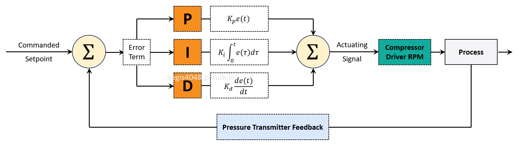
Figure 43: PID loop control system for pressure regulation. The algorithm continuously adjusts driver RPM based on pressure transmitter feedback, using proportional, integral, and derivative calculations to minimize deviation from the target pressure setpoint.
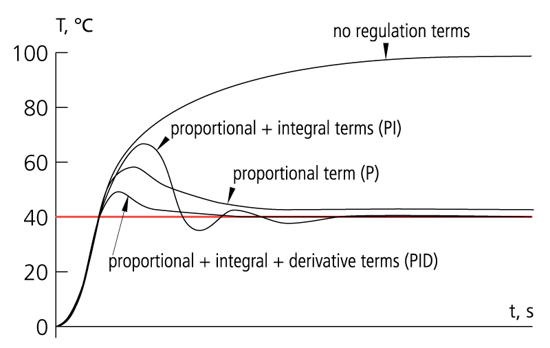
Figure 44: Temperature control PID loop with 40°C setpoint (red line), shown for illustrative purposes (not a compressor application). The x-axis shows time progression as the algorithm dynamically adjusts control parameters to minimize deviation from the target temperature, demonstrating characteristic convergence behavior through proportional, integral, and derivative actions.
8.2. RPM Control
The PID loop in the PLC sends a target RPM signal to the compressor driver to ramp up or down based on suction pressure. But how is this target RPM physically achieved? The underlying RPM control mechanisms differ entirely between electric and gas engine models.
-
Electric
Electric compressor models use Variable Frequency Drives (VFDs) to control RPM by adjusting the frequency (Hz) and voltage of the power supplied to the motor. Motor speed is directly proportional to input frequency. For example, if a motor is rated for 1800 RPM at 60 Hz, then at 30 Hz it will run at ~900 RPM, at 45 Hz ~1350 RPM, and at 72 Hz ~2160 RPM—assuming the motor and compressor are rated for overspeed. By changing frequency in real time, the VFD controls compressor RPM without mechanical linkages.
This allows the compressor to respond precisely and quickly to process demands. If suction pressure rises, the VFD increases frequency (Hz) to raise RPM and move more gas—for instance, from 1200 RPM to 1800 RPM. If pressure drops, the VFD lowers frequency to reduce speed and avoid over-compression. This level of control enables more stable pressure regulation management compared to engine-driven systems, which rely on slower, mechanical fuel and throttle adjustments.
-
Gas Engine
Gas engine-driven compressors control RPM using a combination of a magnetic pickup sensor (shown in Figure 44A), a governor system, and an Air-Fuel Ratio Controller (AFRC). The magnetic pickup detects engine speed by sensing gear teeth or flywheel movement and sends this RPM signal to the PLC. The PLC uses this input—along with process data like suction pressure—to determine whether to increase or decrease engine speed. However, the engine does not receive direct RPM commands. Instead, the PLC sends control signals to mechanical components that influence speed indirectly.
The governor adjusts the throttle to regulate how much fuel gas is delivered to the engine. When suction pressure rises, the PLC signals the governor to increase fuel flow, raising RPM. When demand drops, it reduces fuel to slow the engine. Operating alongside the governor, the AFRC controls the air-to-fuel ratio, ensuring stable combustion and reducing emissions. This is especially important when a catalyst is installed, since improper air-fuel balance can reduce catalyst efficiency or cause damage.
Compared to electric compressor models, RPM control in gas engine systems is slower and less precise. Electric units use VFDs that directly adjust motor frequency (Hz), allowing instant RPM changes based on real-time suction pressure or flow. In contrast, engine-driven compressors rely on slower mechanical and pneumatic responses, which can introduce delays during rapid load swings and limit fine pressure control.
The presence of additional control components—MPU, governor, and AFRC—contributes to the reason why gas engine models require more frequent maintenance than electric units, which have fewer moving parts and simpler control architecture.
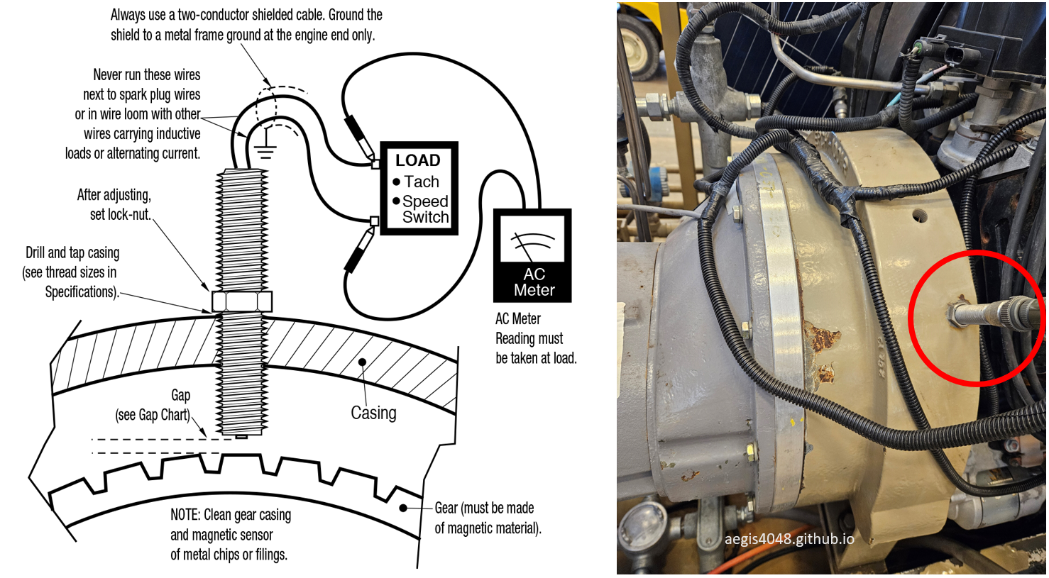
Figure 44A: Illustration of a magnetic pickup unit (MPU) that detects compressor RPM and sends it to PLC for RPM control feedback. Image on the right is an MPU installation on a gas-engine oil-flooded screw compressor. Left diagram from: FW Murphy
8.3. Recycle mode
In VRT applications maintaining 2-4 psig, recycle mode maybe set to activate when pressure falls below 2 psig - a critical threshold since VRTs require minimum 1 psig to prevent liquid overflow into gas lines. The system activates recycle mode before shutdown—shutdown is a last resort—to maintain continous opereation
During recycle mode, two primary actions occur. First, the driver RPM reduces to minimum sustainable levels. Second, the recycle valve opens (either electric type as shown in Figure 19 or pneumatic type in Figure 21), redirecting discharge gas back to suction. Before reaching suction, the recycle gas passes through a pressure reducing regulator (PR-1000, shown in Figure 15) to prevent high-HP shutdown. See Figure 45 for example telemetry data showing driver RPM change with recycle mode activation.
Oil-flooded screw compressors achieve 100% turndown capability through recycle valve operation. Turndown refers to the percentage reduction possible below a compressor's maximum design flowrate without triggering shutdown. The recycle system enables complete (100%) redirection of discharge gas back to suction.
While recycle mode maintains continuous operation, it carries an energy penalty - the compressor repeatedly recompresses and depressurizes the same gas volume by consuming energy (electricity/fuel gas). This trade-off preserves two critical operational benefits over complete shutdowns:
Preseving Heat: Compression generates heat that help maintain unit temperature, preventing potential gas condensation into liquid and lube oil contamination. A complete shutdown typically takes 0.5-3 hours (load-dependent) to regain sufficient operating temperature after restart, during which condensed gas may compromise lube oil quality. Figure 57 shows temperature telemetry data in which a unit took 35 minutes to regain temperature from 65°F to 182°F upon restart after a 12-hr shutdown.
Response Readiness: Drivers cannot instantly accelerate from 0 RPM to operational speeds (1200-2000 RPM). While electric models achieve faster ramp-up than gas engines, maintaining minimum rotation ensures immediate response to process demands.
However, prolonged recycle is not desirable for two reasons:
Decreased Economic Efficiency: Recycle mode triggers when there is not enough volume to pull from a source vessel. When the driver "ramp-up" setpoint pressure is reached, the rotors will spin at maximum RPM until the pressure drops to the "slow-down" setpoint. If the unit is oversized, it may run at full RPM for, say, 2 minutes, then spend 8 minutes idling in recycle mode. During this 8-minute span, energy is wasted (electricity/fuel gas) to keep the unit operating without discharging any gas. This leads to unnecessary resource consumption, both in energy and compressor rental costs. Downsizing to a smaller unit can solve this problem. Unfortunately, VRU's are low priority for most operators, and downsizing is almost never done in a timely manner (I wrote an article on this topic: Predicting VRU Economics/Downsizing Timing For Declining Wells).
Temperature Control Challenges: Electric models face low temperature risks that can lead to lube oil contamination due to insufficient heat generation during recycle mode. Recycle is triggered when the PLC detects low pressure, usually measured at the top of a vessel or on the suction line, indicating low available gas volume. With low volume, there is limited compression occurring, and thus not enough heat is produced to keep the unit hot. In contrast, gas engine models are prone to high temperature shutdowns during recycle. Since the gas engine uses a single driver (engine crankshaft) to power both the rotors and the fan, a reduction in rotor RPM also lowers fan RPM. Although compression heat drops during recycle, the heat from fuel gas combustion remains significant, which can cause temperatures to rise above the cooler's reduced capacity at the redeuced RPM, and trigger a high temperature shutdown. These issues are discussed in greater detail in Section 9.
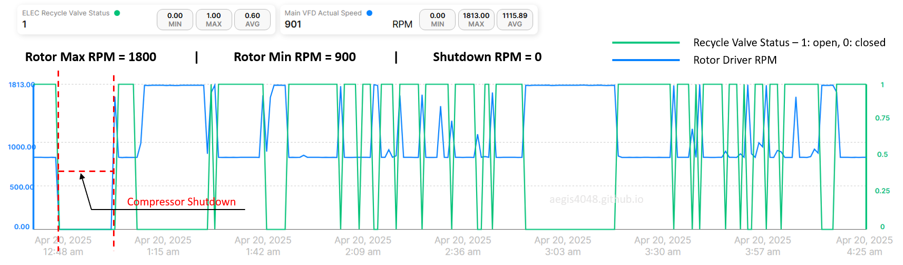
Figure 45: Telemetry data showing rotor driver RPM change with recycle valve status. 1 means recycle valve open, 0 means closed. The driver goes full max 1800 RPM when the "ramp-up" setpoint pressure is reached. When the PLC sends a recycle mode signal, it slows down to the minimum sustainable RPM before shutdown, 900 RPM. The RPM becomes 0 when the unit shuts down. This specific data shows that recycle mode was active for 60% of the 3 hr 45 min time span between 12:40 AM and 4:25 AM, indicating a potential opportunity to downsize the unit.
8.4. Pressure setpoint scenarios
This section shows example source vessel pressure target and recycle setpoint scenarios. The target pressure is the desired pressure a compressor maintains by adjusting driver RPM, controlled by a panel receiving feedback from a pressure transmitter (PT). Location of PT installation depends on application:
PT on source vessel required for:
Low-pressure applications (tank vapor recovery, VRT vapor recovery) where pipeline friction losses would distort readings
ESP casing drawdown (requires 70-90 psig casing pressure, above compressor's 50 psig suction limit)
PT on compressor suction scrubber sufficient for:
Applications within 50 psig suction limit where friction losses are negligible (heater treater vapor recovery, separator drawdown, SRP casing drawdown)
Note that the setpoints presented in this section are examples - actual values may vary based on operational needs, but all shown scenarios are plausible:
8.4.1. VRT vapor recovery
The above discussions on PID loop (Section 8.1) and recycle mode (Section 8.3) used VRT vapor recovery scenario as an example. VRTs typically require 2-4 psig operating range. Above 4 psig risks a chance of gas blowby to tanks and trigger venting/flaring, while below 2 psig risks a chance of liquid overflow to gas line, and into a VRU suction scrubber, potentailly triggering high liquid level shutdown on a VRU. This is due to the unique design of a VRT, which I do not cover in detail here.
Figure 46 and 47 below shows a simplified P&ID and layout diagram of a VRT vapor recovery system. Assuming 5 psig is the maximum pressure you want on a VRT (5 psig is for liquid level control, VRTs typically have 75-150 psig MAWP rating), there will be a BPV set at 5 psig for overpressure relief to combustor during compressor shutdown or volume surge. The VRU targets to maintain the VRT pressure between 2-4 psig by ramping up/down a VFD. Gas flows preferentially to the VRU side due to its lower suction pressure (2-4 psig) compared to the flare side BPV's 5 psig resistance, making the VRU the path of least resistance. Refer to Note 3 for working principles of flare/combustor relief.
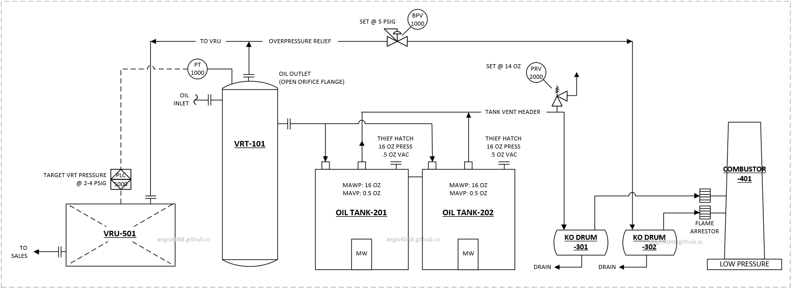
Figure 46: Simplified P&ID of a VRT vapor recovery system showing pressure control architecture. The vapor recovery unit (VRU) has a PLC that monitors VRT pressure via transmitter (PT) and adjusts VFD speed to maintain 2-4 psig target operating range. The system has a back pressure valve (BPV) that opens at 5 psig to prevent VRT overpressurization by relieving excess gas to flare. The tank has a thief hatch set at tank MAWP for atmospheric vent and a secondary PVRV set slightly below hatch rating for flare relief. The atmospheric tank receives only minimal flash gas volumes because the VRT already processed most flash gas volumes. The small remaining volumes (resulting from 2-4 psig system pressure drop) are routed to low pressure combustor.
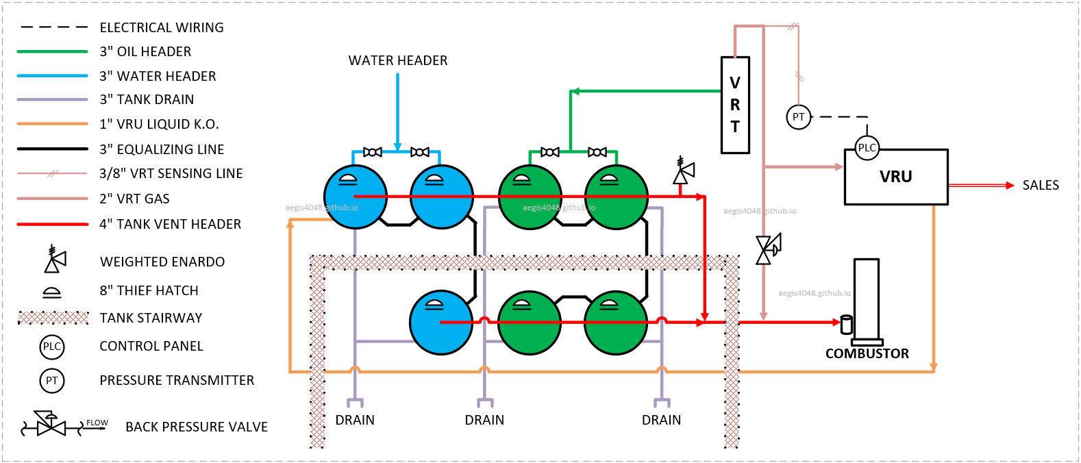
Figure 47: Example layout of an upstream production facility VRT vapor recovery system. The 2" VRT gas line flows to the VRU during normal operation, switching to the combustor when the VRU is down. The BPV opens during pressure upset or VRU shutdown. A sensing line from the VRT top connects to a pressure transmitter (PT) wired to the compressor PLC. The VRT captures most flash volume, while residual tank gas flows to the combustor via the 4" tank vent header. The weighted Enardo PRV on the vent header provides atmospheric venting during pressure surges before thief hatch activation.
-
PT install location
VRTs usually have a sensing line that comes from the top of VRT and down to the ground level. A PT can be either installed on this sensing line and wired to a compressor PLC, or just use the internal PT on the compressor suction scrubber. Either is fine for VRT applications.
-
SCV required?
Suction control valve (SCV, see Section 7.9 for working principles) is not needed as VRT pressure will never exceed 50 psig (compressor max suction pressure). In fact, pressure drop from passing through the SCV decreases flowrate capacity due to reduced pressure (see Table 1). VRT's only have 2-4 psig pressure available, 0.5-1 psig pressure drop from SCV can be detrimental to flowrate capacity.
VRT Vapor Recovery Set Point Scenarios
- Above 5 psig: High suction pressure alarm, potential flaring
- Between 2-5 psig: Normal operating range
- 3 psig: Target setpoint
- 2 psig: Recycle setpoint
- Between 1-2 psig: Recycle operating range
- Below 1 psig: Low suction pressure shutdown, system check and waiting to autostart
8.4.2. Tank vapor recovery
Different pressure control applications (tanks, heaters, separators, wellheads) require different operating pressures. The most challenging is vapor recovery from atmospheric storage tanks due to their extremely low operating range (measured in ounces).
These tanks (usually 8-16 oz MAWP, API 12F design) have oversized vent headers (4"-6") to minimize friction loss. Preserving their minimal pressure is critical to avoid flaring and thief hatch openings.
Assume a 16 oz MAWP tank vapor recovery system shown in Figure 48 and 49. Each tank will have a thief hatch with 16 oz setpoint, and an 14 oz Enardo valve (essentially functions like a back pressure valve) that dumps to flare during process upsets (see to Note 3 for working principles of flare/combustor relief). The Enardo setpoint is intentionally set lower than thief hatch setpoint, because these hatches do not automatically close once they are set off (thief hatch emissions are the biggest emission source in the oil and gas industry). A proper tank design should aim to never set off a thief hatch. A VRU can target 5 oz pressure on the tank. When pressure rises above 5 oz, compressor driver will speed up to pull gas and decrease pressure from the tank. A recycle mode can be set at 4 oz to prevent overdrawing the tank and introduce oxygen ingress.
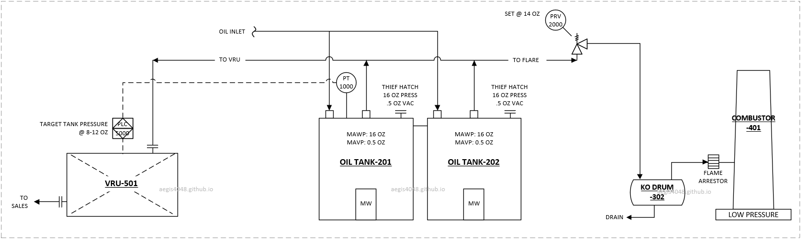
Figure 48: Simplified P&ID of atmospheric tanks vapor recovery system showing pressure control architecture. The VRU PLC targets maintaining 8-12 oz tank pressure. The PT installs directly on the tank top and wires to the PLC to avoid false readings from friction loss. The key difference from the VRT P&ID in Figure 46 is that the PRV here acts as a back pressure valve set at 14 oz, compared to 5 psig BPV in the VRT example. These are usually weighted Enardo PRVs that maintain small back pressure until reaching their set point. Gas flows to the compressor side due to its lower resistance compared to the PRV side.
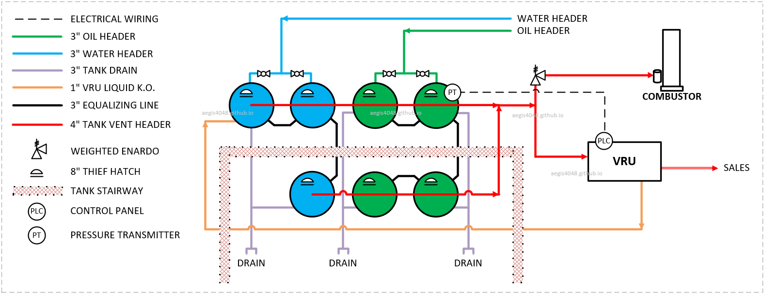
Figure 49: Example layout of an upstream production facility tank vapor recovery system. The red line is the 4" tank vent header that can either go to VRU during normal operation, or to flare through the Enardo valve during pressure upsets. Note that the pressure transmitter (PT) is installed directly on top of a tank, and wired to a compressor PLC to avoid false pressure readings due to friction loss.
-
PT install location
PT must be installed on tank roof or vent headers (not ground level) and wired to compressor PLC. Even 1-2 oz friction loss in piping can cause false low readings, triggering unnecessary flaring (e.g., compressor reads 6 oz when tank is at 7 oz, activating 7 oz Enardo).
-
SCV required?
Suction control valve (SCV, see Section 7.9 for working principles) should not be installed - tank systems cannot tolerate any friction losses.
Tank vapor recovery setpoints for compressor targets, Enardo PRVs, and thief hatches are determined by the tank's MAWP. Below are typical vapor recovery setpoint scenarios for 8 oz vs. 16 oz MAWP tank ratings:
8 oz MAWP tanks: Provide minimal control margin. When targeting 3 oz, the compressor PID loop must maintain tight pressure control between 2-5 oz to prevent flaring, leaving only 3 oz of operating margin. While compressors handle most emissions, some gas volumes may still be intermittently flared or vented during flow or operational upsets.
16 oz MAWP tanks: Offer significantly more control room, allowing for more stable pressure management and reduced venting events compared to 8 oz tanks. When targeting 5 oz, operating range can be between 4-13. This is much bigger margin than 8 oz tank.
8 oz Tank Vapor Recovery Set Point Scenarios
- Above 8 oz: Thief hatch opens, vent to atmosphere
- Betweem 6-8 oz: Thief hatch simmering
- 6 oz: PRV fully open to combustor
- Betweem 5-6 oz: PRV simmering
- Betweem 2-5 oz: Normal operating range
- 3 oz: Target setpoint
- 2 oz: Recycle setpoint
- Betweem 1-2 oz: Recycle operating range
- Below 1 oz: Vacuum safety triggers, potential oxygen ingress problems
16 oz Tank Vapor Recovery Set Point Scenarios
- Above 16 oz: Thief hatch opens, vent to atmosphere
- Betweem 14-16 oz: Thief hatch simmering
- 14 oz: PRV fully open to combustor
- Betweem 13-14 oz: PRV simmering
- Betweem 4-13 oz: Normal operating range
- 5 oz: Target setpoint
- 4 oz: Recycle setpoint
- Betweem 1-4 oz: Recycle operating range
- Below 1 oz: Vacuum safety triggers, potential oxygen ingress problems
8.4.3. Heater vapor recovery
BEFORE YOU READ: This section assumes: (1) a compressor maximum suction of 50 psig (mechanical limit of Leroi HG series compressors), and (2) reader familiarity with suction control valve operation (Section 7.9).
Heater treaters operate at much higher pressures (30-70 psig) compared to VRT systems (1-5 psig) or atmospheric tanks (1-16 oz), giving much bigger operating margins for compressor operation setpoints.
Similar to VRT and tank applications, the heater gas line splits into two paths: 1) to VRU suction (main path), and 2) to flare with a back pressure valve (BPV) set higher than the target suction pressure. This pressure differential between the suction pressure and the BPV setpoint ensures vapors flow to the VRU during normal operation (path of least resistance), while automatically diverting to flare for pressure relief during VRU shutdowns or process upsets. See Figure C below for an example telemetry data showing pressure relief to flare during VRU shutdown. See Figure 50, 51, and 52 for example P&IDs for BPV (BPV-6001) installations on flare side.
Heater vapor recovery differs from VRT/tank applications in potentially requiring a suction control valve (SCV) (see Section 7.9 for SCV working principles). Given heaters typically operate at 20-70 psig and compressors have 50 psig suction limits:
- Above 50 psig: SCV mandatory to reduce pressure below compressor suction limit
- 40-50 psig: SCV "highly recommended" due to inevitable occasional pressure swings
- 20-40 psig: SCV optional but recommended for upstream applications where:
- Separators upstream of a heater may not fully absorb flow variations (typical 2x-6x normal swings)
- Compressor response may lag behind sudden gas surges
- Historic data shows severe pressure fluctuations
While compressors can adjust RPM to maintain target pressure, sudden surges often exceed this capacity. Operators should review heater telemetry history - if uncertain, the $1,500-$2,500 SCV installation cost is typically justified versus frequent shutdown risks. Retrofit remains an option if initial SCV-less operation proves problematic.
SCV installation also helps maintain VRU operation even during flare activation. When flare engages (indicating system pressure exceeded BPV setpoint), the SCV prevents compressor shutdown by isolating suction pressure from system (heater vessel + heater gas line piping) pressure. Figure 50 shows a heater treater system without SCV (25 psig target, 110 psig BPV) where flow surges may cause complete VRU shutdown - system pressure, including the compressor suction pipe, equalizes up to BPV setpoint, triggering high HP/suction pressure shutdowns and 100% flare diversion.
Figure 51 demonstrates the SCV-equipped system where the valve physically isolates compressor suction pressure from upstream system pressure. During surges, the SCV maintains suction pressure at ≤25 psig (regardless of heater/BPV side pressure) by throttling flow, while allowing only excess volume beyond compressor capacity to reach the 110 psig BPV setpoint and divert to flare. This enables continuous VRU operation handling most surge volume (e.g., 70%), with only the remainder (e.g., 30%) flaring - a critical improvement over the non-SCV configuration's complete shutdown.
Figure 52 demonstrates a specialized configuration where operators maintain heater pressure at 70 psig (above the compressor's 50 psig suction limit) using two pressure controls: (1) a 70 psig BPV on the suction line, and (2) an SCV set below the limit (e.g., 25 psig). While uncommon, this setup serves specific cases where high heater pressure must be preserved alongside VRU operation, creating three distinct pressure zones: heater vessel itself (70 psig), SCV-regulated compressor suction (25 psig), and flare protection (110 psig).
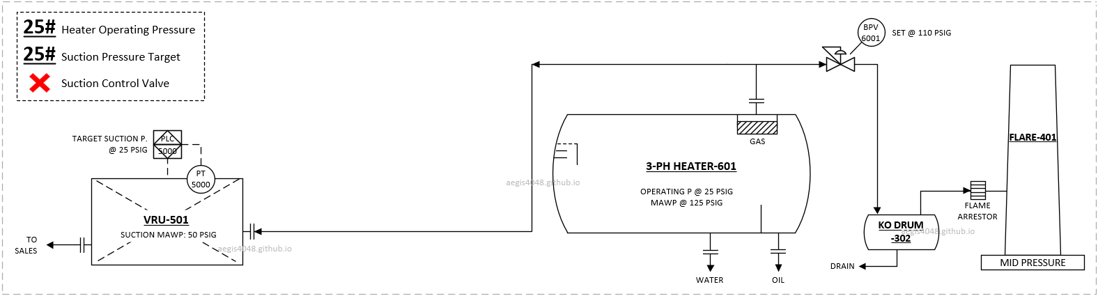
Figure 50: Simplified P&ID of heater treater vapor recovery system showing pressure control architecture. A pressure transmitter (PT) is installed on the suction scrubber line on a compressor skid, and wired to the PLC. The PLC aims to maintain 25 psig pressure on the suction line. The flare line has a BPV set at 110 psig (below the 125 psig heater MAWP) to divert gas to flare during compressor shutdown or volume surges. This system doesn't have SCV, and are vulnerable to high HP/suction pressure shutdown during process upsets. When shutdown is triggered, 100% volume is diverted to flare.
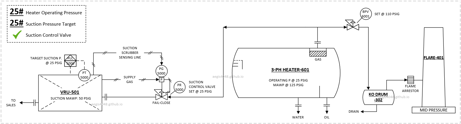
Figure 51: This SCV-equipped version of the system in Figure 50 prevents compressor shutdowns during sudden flowrate/pressure surges by maintaining suction pressure ≤25 psig. When surges exceed compressor capacity, the SCV throttles to protect the VRU while diverting only excess volume to flare through the 110 psig BPV.
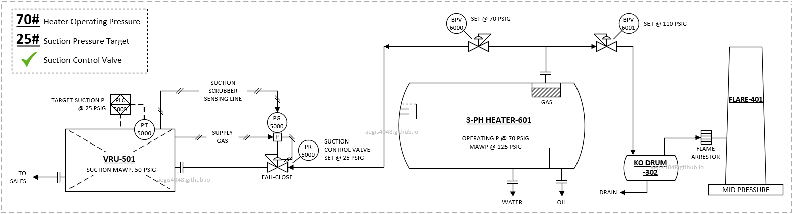
Figure 52: Similar setup as Figure 51, with the presence of an additional BPV set at 70 psig on the compressor line, in case an operator wants to keep heater pressure above compressor max suction of 50 psig. The pressure of the heater until the SCV inlet will normally operate at 70 psig, while downstream of the SCV will be kept at 25 psig to prevent high suction pressure shutdown.
-
PT install location
Compresssor-skid-contained PT on a suction scrubber is good enough. Friction loss is negligible compared to the operating pressure of the heaters. Targeting a pressure on suction scrubber will essentially target heater pressure as well.
-
SCV required?
Suction control valve (SCV, see Section 7.9 for working principles) may or maynot be needed. Review historic pressure data to make a judgement call.
30# Heater Treater Vapor Recovery Set Point Scenarios
- Above 50 psig: Compressor high suction pressure shutdown
- Betweem 32-50 psig: Operating margin
- Betweem 28-32 psig: Normal operating range
- 30 psig: Target setpoint
- 28 psig: Recycle setpoint
- Between 20-28 psig: Operating margin
- Below 20 psig: Low pressure shutdown (flexible as long as above 20 psig)
8.4.4. Separator drawdown
Separator drawdown artificially lowers salesline backpressure on the wellhead by installing a compressor on a gas outlet line of a primary separator. A primary separator between the wellhead and salesline performs bulk gas/liquid separation. The separator experiences salesline backpressure (e.g., 150 psig), which propagates to the wellhead, wellbore, and reservoir, reducing flow rates as backpressure increases.
Installing a compressor directly downstream of a compressor isolates the wellhead from 150 psig salesline pressure. Instead, the wellhead sees reduced 0-50 psig compressor suction pressure. The compressor boosts pressure to meet salesline requirements while creating significant wellhead drawdown, resulting in production uplift.
This technology can be used on: 1) naturally flowing wells, 2) liquid-loaded wells, 3) plunger-lift wells and 4) wells lacking pipeline infrastructure for buyback gas or facing expensive buyback sources (each of these topics deserve more in-depth discussion, but it's not the focus of this article)
Unlike the VRT, Tank, and Heater vapor recovery applications shown above that has a BPV set to dump to flare, separator gas bypasses the compressor during shutdowns/upsets, flowing directly to salesline.
Take Figure 53 as an example. During normal operation, all separator gas flows to the compressor suction side (path of the lowest resistance) and the wellhead sees minimal back pressure. During compressor shutdown or volume surge, check valve CHK-6000 essentially functions as a BPV that relieves excess pressure to salesline. The check valve won't open until the separator pressure reaches 150 psig. Compressor shutdown or process upsets make separator pressure to build upto the salesline pressure, exerting high backpressure on the wellhead and negatively affecting hydrocarbon production.
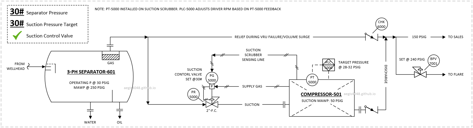
Figure 53: Simplified P&ID showing primary separator drawdown system. The 150 psig salesline pressure creates backpressure that propagates through the separator and wellhead (WH not shown) to the reservoir, reducing production flowrates. The separator gas line splits into two paths: (1) compressor suction during normal operation (when sized for full capacity), and (2) salesline relief during compressor shutdown or surges. Check valve CHK-6000 serves as a backpressure valve, remaining closed until separator pressure reaches salesline pressure. During compressor shutdown, wellhead pressure builds up from normal 30 psig suction to full 150 psig salesline pressure. The system has secondary relief to flare through BPV-7001 set at lower pressure (240 psig) than the primary separator MAWP (250 psig) during potential salesline process upset events. The SCV on the suction line protects the compressor from potential high HP/suction pressure shutdown due to wellhead pressure/flowrate swings.
-
PT install location
Compresssor-skid-contained PT on a suction scrubber is good enough. Friction loss is negligible compared to the operating pressure of the separators. Targeting a pressure on suction scrubber will essentially target heater pressure as well.
-
SCV required?
Suction control valve (SCV, see Section 7.9 for working principles) is "very highly recommended" as separators separators experience constant 2x-6x pressure/flowrate swings directly from wellheads. Without SCV protection, compressors suffer frequent high-HP/suction pressure shutdowns.
The control panel pressure sepoints are very similar to those of heater vapor recovery applications. Note that these setpoints are just an example, real setpoints can be different based on operational needs. For example, setting 5 psig target suction pressure will create bigger pressure drop and production uplift, but will require additional liquid pump due to separator lacking minimum 20 psig pressure to dump liquid to downstream process vessels. Higher setpoint pressuress can be set upto 50 psig to either 1) ensure liquid dump with out a pump, or 2) increase flowrate capacity (high suction pressure increases capacity, see Table 1)
30# Separator Drawdown Set Point Scenarios
- Above 50 psig: Compressor high suction pressure shutdown
- Betweem 32-50 psig: Operating margin
- Betweem 28-32 psig: Normal operating range
- 30 psig: Target setpoint
- 28 psig: Recycle setpoint
- Between 20-28 psig: Operating margin
- Below 20 psig: Low pressure shutdown (flexible as long as above 20 psig)
5# Separator Drawdown Set Point Scenarios (Pump Required)
- Above 50 psig: Compressor high suction pressure shutdown
- Betweem 6-50 psig: Operating margin
- Betweem 4-6 psig: Normal operating range
- 5 psig: Target setpoint
- 4 psig: Recycle setpoint
- Between 1-4 psig: Operating margin
- Below 1 psig: Low pressure shutdown
8.4.5. Casing drawdown
The purpose of casing drawdown is to eliminate gas interference in tubing side with downhole pumps like sucker rod pumps (SRPs) and electric submersible pumps (ESPs). Gas interference reduces pump efficiency, damages equipment, and forces frequent shutdowns for repairs. Traditional fixes—such as installing downhole separators, optimizing pump placement, or increasing wellhead back pressure—are limited because gas must still travel up the tubing alongside liquids. Casing drawdown addresses the root cause by opening the casing side, creating a dedicated gas relief path.
Consider a wellhead with 150 psig sales line backpressure at the separator. The tubing side with the pump sees 150 psig salesline back pressure. Casing side connected to a compressor inlet, sees much lower back pressure (0-50 psig suction pressure). Gas flows to the path of leat resistance - the casing side. The wellhead now functions like a giant two-phase separator, in which gas exits through the casing (to compressor) and liquids through the tubing (via a pump), eliminating gas interference problems.
While fixing gas interference in downhole pumps is the main purpose of casing drawdown, it also increases gas flow rates. Unlike conventional systems where gas harms pumps, here it flows exclusively up the casing. Reducing casing backpressure from 150 psig to 5 psig typically boosts gas flow rates 2x-6x. This is similar to increasing flowrates by lowering salesline backpressure through primary separator drawdown, explained in Section 8.4.4.
One operational concern for casing drawdown is potential liquid flow up the casing. Normally wells on artificial lift lack pressure to constantly pump liquid on their own, but pressure buildup from liquid accumulation, slug flow, or increased gas flow rate post-compression may occasionally cause gas to exceed critical flow rate (minimum gas flow rate needed to lift liquid). This can make liquids not captured by the tubing-side pump flow up the casing, potentially triggering high liquid level shutdowns on the compressor (see Figure 33), as the suction scrubber isn't designed as a bulk separator.
Predicting liquid flow rate up the casing is difficult as these come from entrained mist or liquid slugs from pressure swings that are difficult to be modeled. An operator may start with or without a test separator, observe how the well responds to casing-side liquid, and determine if a permanent external scrubber is needed. These vessels can be simple trailer-mounted test separators with hose connections.
Casing drawdown is applicable for either SRP or ESP systems.
8.4.5.1. SRP Casing drawdown
Figure 54 below shows an example P&ID for SRP well casing drawdown, with test separator and 5 psig suction target pressure. 5 psig is not enough pressure to dump liquid to downstream process vessels, hence a liquid pump is installed to handle the liquids. Setting it at a higher pressure of 20 psig will ensure liquid dump without the pump, but production uplift will be smaller due to smaller pressure drawdown. Note that the test separator installation is optional, depending on well response.
Figure 55 is a similar setup, but without the test separator due to minimal casing side liquid volume.
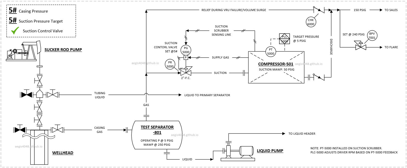
Figure 54: Simplified P&ID for SRP well casing drawdown. Compressor on casing side removes gas interference problems by driving gas to the casing side, instead of tubing. Optional test separator handles liquid (entrained mist/flow swings) that could trigger high liquid level shutdown on a suction scrubber. 5 psig suction requires liquid pump for test separator drainage. Relief line to flare handles surge/shutdowns. PT-5000 on scrubber maintains pressure via PLC-5000.
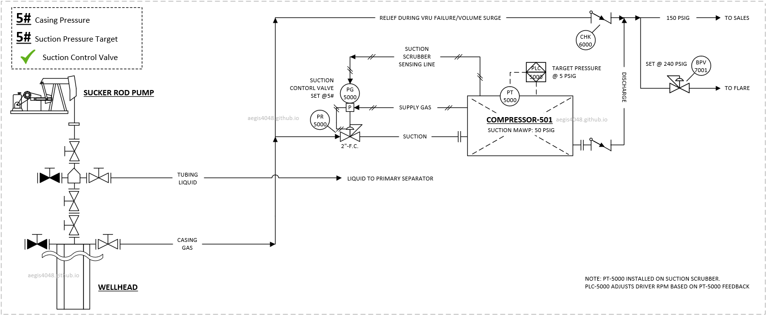
Figure 55: Similar setup as above, but test separator is not installed due to minimual casing side liquid flow that can be handled by compressor suction scrubber.
-
PT install location
Compresssor-skid-contained PT on a suction scrubber is good enough. Friction loss is negligible compared to the operating pressure of the casing. Targeting a pressure on suction scrubber will essentially target heater pressure as well.
-
SCV required?
Suction control valve (SCV, see Section 7.9) is "mandatory" as the compressor is directly exposed to wellhead that experiences constant 2x-6x pressure/flowrate swings. Without SCV protection, compressors suffer frequent high-HP/suction pressure shutdowns.
5# Casing Drawdown Set Point Scenarios
- Above 50 psig: Compressor high suction pressure shutdown
- Betweem 6-50 psig: Operating margin
- Betweem 4-6 psig: Normal operating range
- 5 psig: Target setpoint
- 4 psig: Recycle setpoint
- Between 1-4 psig: Operating margin
- Below 1 psig: Low pressure shutdown
8.4.5.2. ESP Casing drawdown
ESP setups differ from SRPs due to requiring 70-90 psig casing pressure, exceeding the 50 psig compressor suction limit. Two implementation methods exist:
1) Install BPV on WH casing flowline
The BPV maintains minimum casing pressure but requires additional valve installation costs.
2) Wire casing PT to compressor PLC (recommended)
Existing casing PTs can be connected to the compressor PLC to control source pressure, similar to Tank vapor recovery systems.
Since casing pressure exceeds compressor suction limits, an SCV must be installed between casing and suction. ESP systems also more frequently require external scrubbers to prevent compressor shutdowns, as ESPs typically handle larger flow rates than SRPs.
See figure Figure 56 for an example P&ID setups.
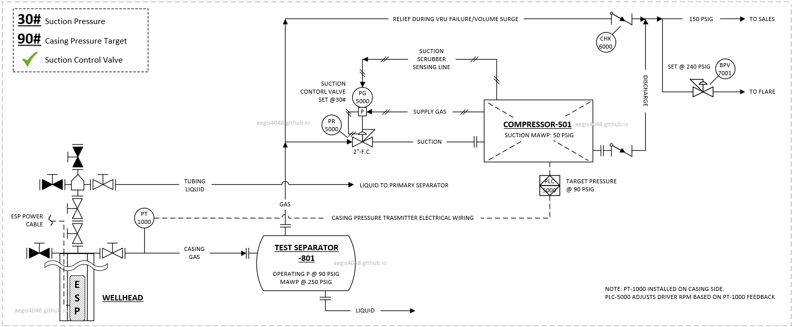
Figure 56: ESP well version of Figure 54 system. Key differences: No liquid pump needed (90 psig casing pressure vs SRP's 5 psig), and external PT-1000 on casing (not compressor suction scrubber) sends feedback to PLC for driver RPM control.
-
PT install location
Eixsting PT on the casing is wired to compressor PLC for target pressure feedback. PT on suction scrubber is inadequate as the suction scrubber will see reduced pressure due to SCV reducing pressure below 50 psig.
-
SCV required?
Suction control valve (SCV, see Section 7.9) is "mandatory" as the casing pressure target exceeds 50 psig max suction pressure limit. For ESP applications, the higher the SCV setpoint, the better because flowrate capacity increases with increasing suction pressure. There's no advantage for maintaining low pressure for SCV setpoint.
80# ESP Drawdown Set Point Scenarios At Casing PT
- Above 90 psig: High casing pressure shutdown (depends on ESP design)
- Betweem 82-90 psig: Operating margin
- Betweem 78-82 psig: Normal operating range
- 80 psig: Target setpoint
- 78 psig: Recycle setpoint
- Between 70-78 psig: Operating margin
- Below 70 psig: Low pressure shutdown (depends on ESP design)
- Between 40-50 psig: SCV setpoint
Note 3: Relief to flare/combustor
Vapor recovery systems aim to capture all vapors from source vessels (tanks, VRTs, heaters, etc.), but VRUs occasionally experience downtime. The continuous flash gas generation builds up pressure that requires a relief point to prevent explosions. During VRU shutdowns, flare/combustors process these gases - burning harmful VOCs into CO2 instead of direct atmospheric venting.
The system design must ensure: (1) during normal operation, gases flow exclusively to the VRU, and (2) during VRU shutdowns or capacity overload, excess volumes automatically divert to flare. This is achieved through a back pressure valve (BPV) on the flare line set sufficiently above the VRU suction target. The BPV creates higher resistance, making the VRU path the least resistant route during normal operation, and diverting excess gas to flare only during process upsets or VRU shutdown. Example P&IDs are shown in Figure A and Figure B. While the detailed valving and piping can be a bit different, the idea is the same. There's a low pressure VRU suction side intended to be used during normal operations, and a high pressure relief side with resistance that opens only during process upsets or VRU shutdown.
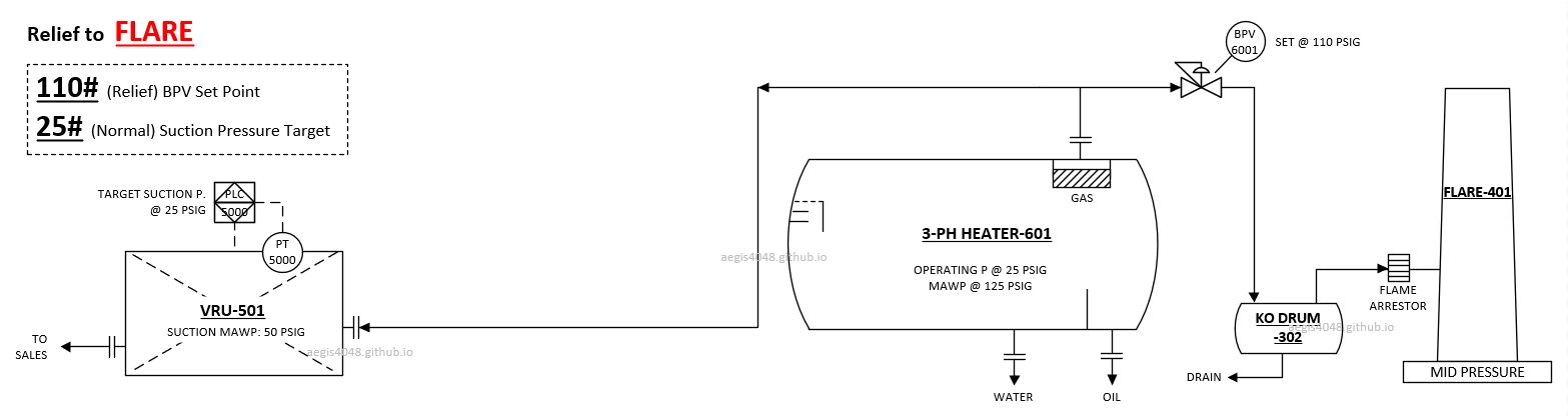
Figure A: Example P&ID of heater treater vapor recovery system with relief to flare. During normal operation, compressor suction maintains lower pressure (25 psig) than the flare side's back pressure valve BPV-6001 (set at 110 psig).
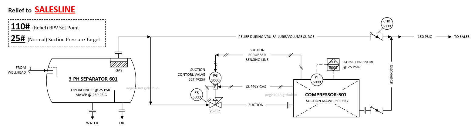
Figure B: Example P&ID of separator drawdown system with relief to sales line operating at 150 psig. The check valve CHK-6000 essentially functions as a BPV set at 150 psig, opening when the separator pressure builds up to 150 psig salesline pressure due to either process upsets or VRU shutdown.
Consider a heater vapor recovery example operating at 25 psig with a 110 psig BPV setpoint shown in Figure A. During VRU shutdown or peak volume surge:
- Initially the system pressure is 25 psig
- VRU suction and heater pressure build up to BPV setpoint (110 psig)
- BPV opens, dumping to flare until pressure drops (ex: ~80 psig)
- Cycle repeats until VRU restarts or surge subsides
Figure C shows telemetry data for this VRU shutdown scenario & relief to flare in a heater treater application. Note that while operating pressures vary, the principle of automatic diversion to flare/combustor via higher resistance remains consistent across tanks, VRTs, heaters, separators, and wellheads.
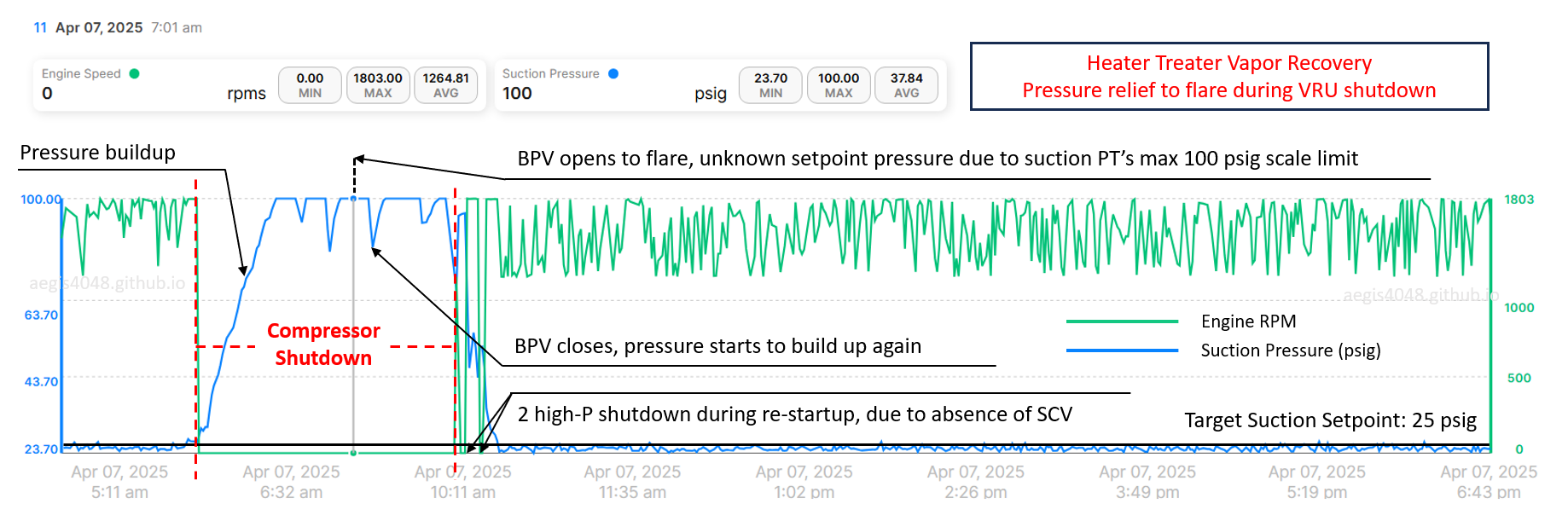
Figure C: Telemetry data showing heater treater pressure relief to flare during VRU shutdown. A pressure transmitter (PT) is installed on the suction scrubber gas outlet line. The PT reading stops at 100 psig due to scale limit between -14.7 to 100 psig. Actual heater pressure exceeded 100 psig during compressor shutdown, reaching the BPV setpoint (say 110 psig). When pressure hits 110 psig, the BPV opens to flare. Pressure drops to ~80 psig when BPV closes (2nd black arrow). After compressor restart, two high suction pressure shutdowns occurred (3rd black arrows) due to built-up pressure from the heater hitting the compressor without SCV regulation (max 50 psig suction limit). Once pressure stabilized, the unit maintained around the target 25 psig suction.
9. Temperature control
BEFORE YOU READ: This section assumes reader familiarity with 3-way thermostatic valve operation (Section 7.4).
Discussion on oil-flooded screw compressor temperature control should be divided into two categories: electric-driven models and gas engine-driven models. The key distinction in temperature management arises from how each model powers the compressor rotors and cooling fan.
Electric (Section 9.1) compressors use two motors to independently to drive the compressor rotors and the cooling fan. This arrangement allows precise, real-time RPM adjustments for BOTH components, optimizing temperature control effectively. The cooling fan has 2 sections, for lube oil and and discharge gas (shown in Figure 59).
Gas engine (Section 9.2) compressors utilize a single engine to simultaneously power both the compressor rotors and the cooling fan. The rotor RPM becomes the primary control target, eliminating the possibility of dedicated real-time RPM adjustments for cooling. Additionally, gas engines generate significant heat from fuel combustion, which, combined with the heat produced from compression, makes temperature control difficult during hot summer seasons. The cooling fan has 3 sections, for lube oil, discharge gas, and engine coolant (shown in Figure 60)
These inherent differences result in distinct temperature control characteristics for each compressor type, summarized in Table 4. Overall, electric models are better than gas engines at handling temperature control, as long as a unit is not oversized. For electric models, timely downsizing is important as well declines to avoid low temperature and lube oil contamination issues. Oversized units experience frequent recycle, which may not generate enough heat to keep the unit hot.
For both compressor types, recycle mode (see Section 8.3) is preferred over complete shutdown for temperature control purposes when the source vessel lacks sufficient gas to draw from. Recycle maintains compressor operation at minimum sustainable RPM (ex: 900 RPM in Figure 57), continuously generating heat from compression to keep the unit warm. In contrast, a full shutdown significantly lowers compressor temperature due to surrounding ambient air cooling, increasing the risk of lube oil contamination from gas condensation at low temperatures (see Section 10).
For instance, Figure 57 shows telemetry data around a 12-hour shutdown. Upon restarting at 12:49 PM, the lube oil temperature was near ambient at 65°F. It took 35 minutes to reach 182°F (by 1:24 PM), then an additional 247 minutes to stabilize at 233°F (thermostatic valve setpoint ~230°F, acceptable valve ±3°F tolerance) by 5:31 PM. During the first 35 mintues [1], condensates definitely formed and contaminated oil as 65°F is just too low. During the later extended warm-up period [2], gas may or may not occured, depending on dew point temperature of the process gas. Due to these thermal challenges, recycle mode is programmed to activate prior to shutdown to maintain optimal compressor temperatures.
A healthy temperature trend for lube oil and discharge gas should look like Figure 58, with the average temperature slightly below the thermostat valve setpoint (e.g., 230°F) and a 5-15°F approach temperature between lube oil and discharge gas. This ensures the gas stays hot enough to prevent lube oil contamination, while also staying below the thermostat setpoint to avoid high temperature shutdown.
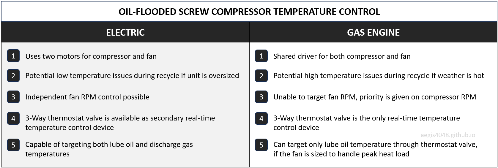
Table 4: Temperature control differences between electric vs. gas engine models. Electric models are better than gas engine models for temperature control, as long as unit is not oversized. Timely downsizing is important as well declines to avoid low temperature issues.
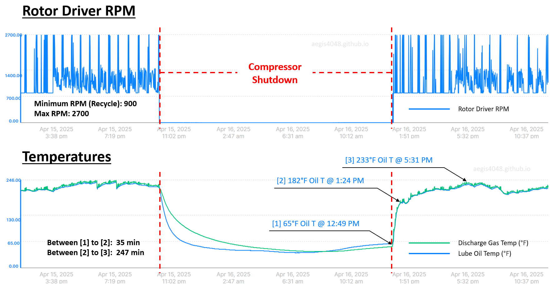
Figre 57: Telemetry data of an electric compressor for VRT vapor recovery around 12-hr shutdown period. In the lower temperature plot, the unit took 35 minutes between [1] and [2] to regain temperature from 65°F to 182°F. During this 35 minutes period, liquid condensation definitely happened due to typically high BTU content (1600-2500 BTU/scf) of VRT gases. During [2] and [3] (247 minutes), condensation could've happened depending on compression ratio and gas BTU content.
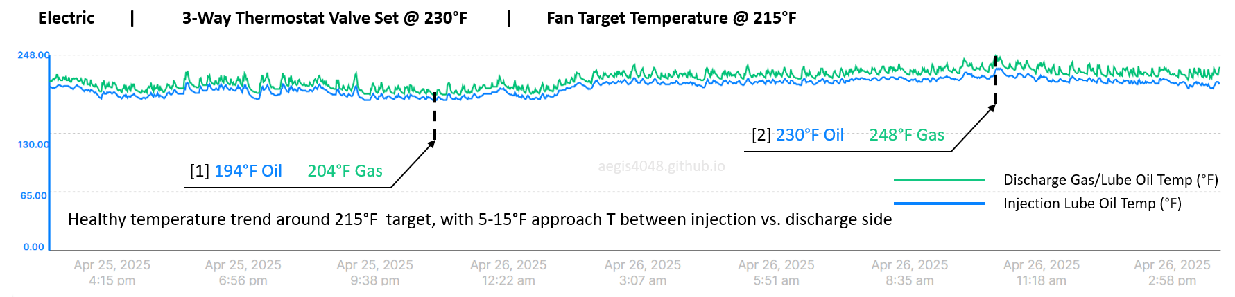
Figre 58: Temperature telemetry data of an electric compressor. The thermostat valve is set at 230°F. The fan has a dedicated motor that targets a 215°F setpoint on the lube oil. The PLC control on fan motor RPM acts as a primary control for oil temperature. The 230°F thermostat acts as a secondary backup control to prevent high temperature if the fan RPM adjustment cannot contain the oil temperature. This occurred in [2], when the temperature nearly overshot 230°F; the thermostat valve intervened as a final control device to contain temperature under 230°F (±3°F tolerance). A healthy temperature control trend should look like this. One thermowell is installed on the injection side of lube oil line (pre-compression), and the other is installed on the 2-phase mixture line of lube oil and gas leaving the compression chamber (post-compression).
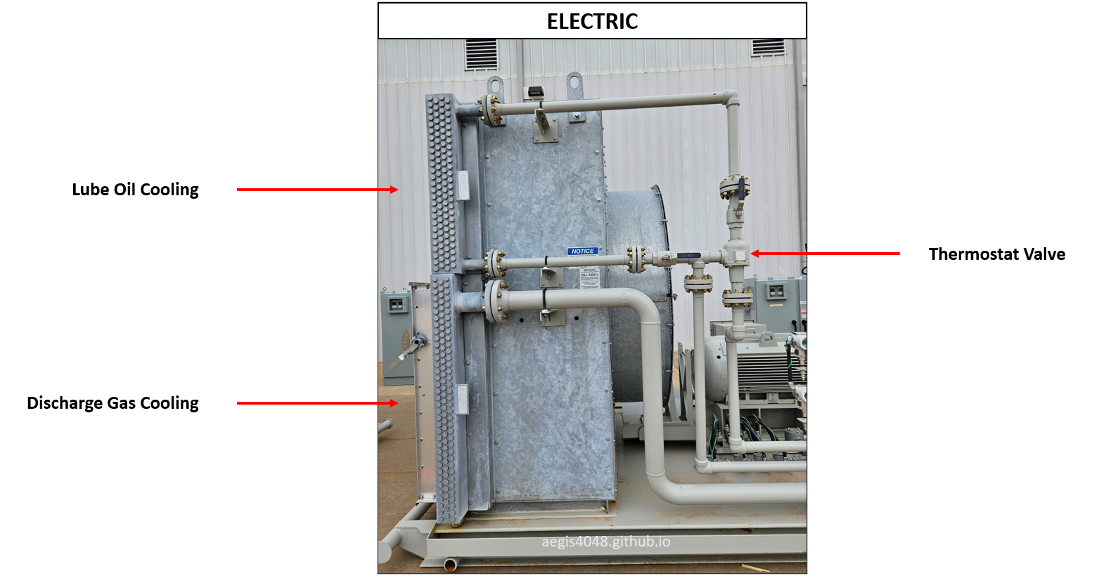
Figre 59: Cooling system for an electric oil-flooded screw compressor. The fan has two sections for lube oil and discharge gas.
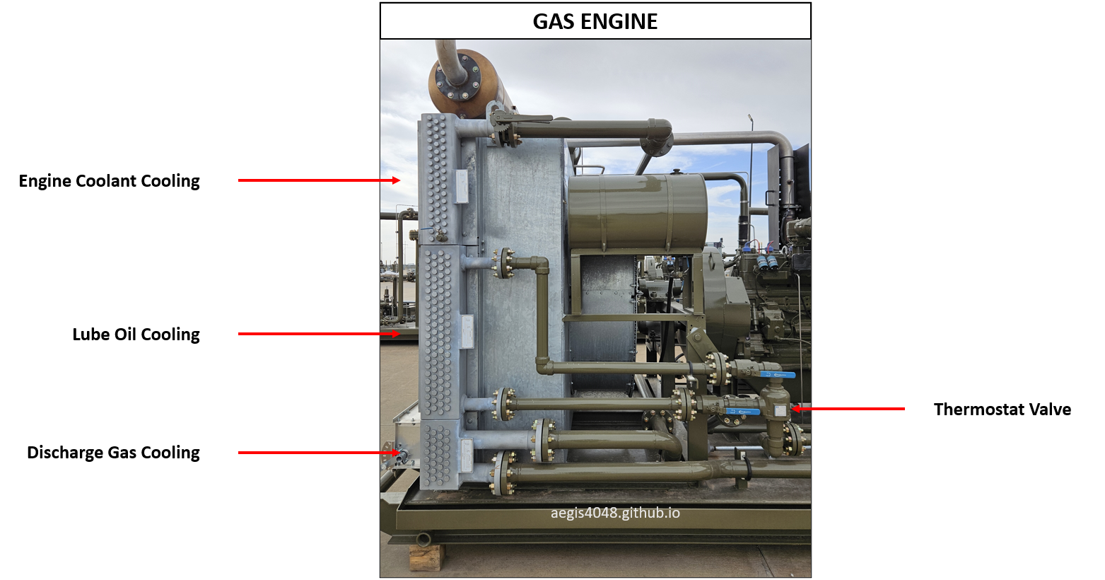
Figre 60: Cooling system for a gas engine oil-flooded screw compressor. The fan has three sections for lube oil, discharge gas and engine coolant.
9.1. Electric models
BEFORE YOU READ: This section assumes reader familiarity with 3-way thermostatic valve operation (Section 7.4) and P&ID flow for electric model compressors (see Type A: Full electric).
Note: For reader clarity, "discharge gas" refers to gases leaving the compression chamber, while "aftercooled gas" refers to gases leaving the fan. The hot discharge gas is cooled inside the fan and exits the skid as cold aftercooled gas.
Electric models use two motor drivers—one for the fan and one for the compressor—allowing independent RPM control for each. This allows for superior temperature management compared to gas engine models. Electrics generate less heat than gas engine models because electric motors do not burn fuel for power. This section explains key characteristics of electric compressors:
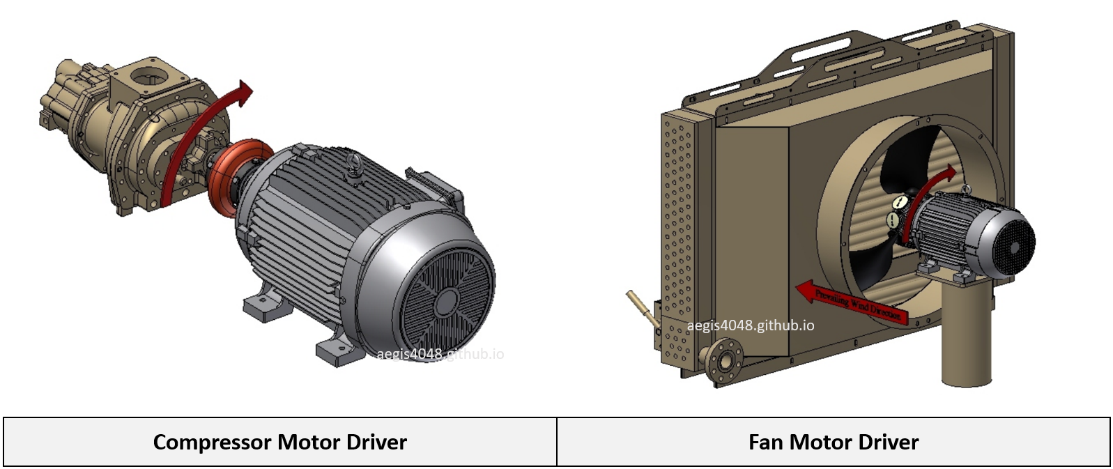
Figre 61: 3D representation of an electric compressor parts. Compressor and cooling fan both have a dedicated motor driver for independent RPM control.
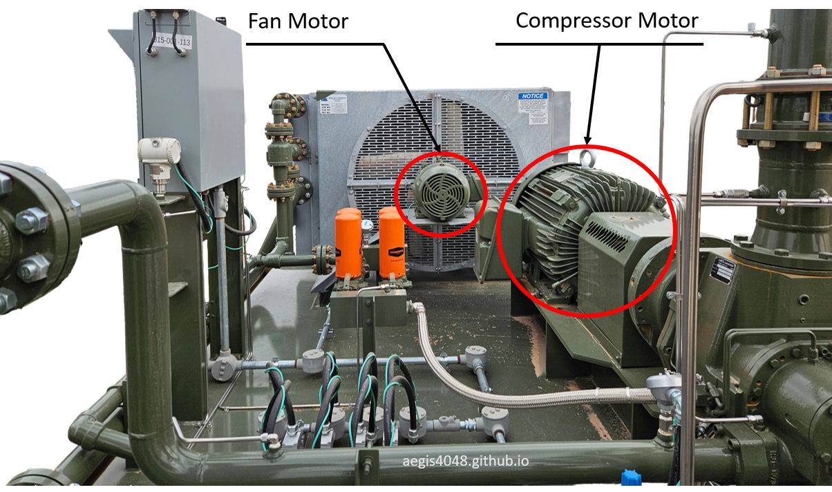
Figre 62: Real-life electric compressor package, highlighting two motors for compressor and cooling fan.
Dual Target Capabiltiy
Electric models offer two real-time temperature control mechanisms: a VFD-controlled fan motor and a 3-way thermostatic valve on the lube oil line. When the fan is properly sized for peak heat loads for the lube oil, the system can manage both lube oil and aftercooled gas temperatures independently.
Consider a scenario where the goal is to maintain 230°F for lube oil on the injection side (pre-compression) and 120°F for gas leaving the compressor skid (post-compression and post-aftercooler). Example P&ID is shown in Figure 15. After compression, the 2-phase mixture of gas and lube oil (purple line) typically experiences a 5-15°F temperature rise, reaching about 240°F (example telemetry data shown in Figure 58). This mixture flows into the discharge scrubber V-300, where gas and oil are separated and directed into different cooler sections (Figure 59) sized according to their heat loads.
The primary temperature control is assigned to the aftercooled gas. A thermowell installed on the post-aftercooler gas line feeds temperature data to the PLC, which adjusts fan RPM to maintain the 120°F target. Suppose 500 RPM achieves this. Meanwhile, the 3-way thermostat valve manages lube oil temperature by mixing bypassed hot oil with cooled oil to maintain the 230°F setpoint. The valve has an expanding/contract thermal element that automatically adjust its position with temperature changes.
However, this control strategy assumes that the cooling effect provided by the fan at 500 RPM is also sufficient for the lube oil. If the cooling capacity at this RPM is inadequate, the thermostat valve cannot regulate temperature effectively—even when fully diverting all oil flow through the cooler—leading to high temperature shutdowns.
Because of this constraint, electric-driven units are often prioritized to maintain lube oil temperature over aftercooled gas temperature. This trade-off is reasonable: lube oil temperature control is critical for compressor protection, whereas deviations in aftercooled gas temperature are negligible once the gas mixes into the larger sales pipeline.
Superior Lube Oil Temperature Management
Electric models offer superior lube oil temperature management by using a dedicated fan motor that targets lube oil temperature — a more critical parameter than aftercooled gas temperature for compressor operation. This means that the aftercooled gas temperature floats, as shown in (Figure 63). Although electric compressors are capable of targeting both aftercooled gas and lube oil temperatures, operations typically prioritize lube oil. The fan-controlled lube oil temperature provides primary regulation, while the 3-way thermostatic valve offers secondary backup control if the fan cannot adequately contain a sudden temperature rise.
This setup is fundamentally better than gas engine-driven models, which lack independent fan RPM control (see Section 9.2 for gas engine temperature control). In engine models, fan speed is tied directly to rotor RPM, meaning the fan turns at full speed whenever the engine runs at full speed, even if maximum cooling is unnecessary. While the 3-way thermostat helps avoid overcooling by diverting flow around the cooler, the real challenge emerges during recycle mode. Unlike electric units, gas engines continue to produce significant heat from fuel combustion even at low RPM (e.g., 900 RPM during recycle, 2400 RPM full speed), while fan airflow also drops due to the reduced engine speed. Reduced air flow due to reduced RPM means ineffective cooling. This imbalance can lead to overheating during recycle, especially in hot conditions — an issue electric compressors are much better equipped to manage.
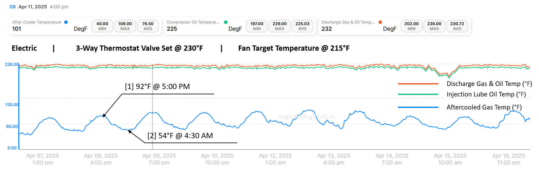
Figre 63: Example telemetry data of an electric compressor. The unit uses a fan with a dedicated motor driver that provides primary temperature control, targeting 215°F on the lube oil. A 3-way thermostat valve provides secondary temperature control in case the fan does not respond quickly enough to sudden temperature rises. Because the fan motor targets only lube oil temperature, the aftercooled gas temperature floats. Aftercooled gas temperature was 92°F during the day at 5:00 PM [1], but dropped to 54°F at night around 4:30 AM [2]. This day-night sine wave pattern repeats daily. While configuring the PLC to target aftercooled gas temperature at a setpoint (e.g., 120°F) would create a flat trend on the aftercooled gas line, lube oil temperature management could become more difficult.
Low Temperature Problems During Recycle
Overall, electric units are superior to gas engine models for temperature control. However, there is one area where electric models are inferior: when a unit is oversized and experiences frequent recycle mode (see Section 8.3), it cannot generate enough heat of compression to maintain a target temperature (e.g., 215°F on lube oil). While this is not an issue if the unit is properly sized, upstream wells typically decline quickly—often seeing production drop by more than half within 6–12 months. Vapor volumes processed by the compressor decline at a similar rate. For example, in a simulation shown in Table 1 of my previous post, vapor volumes on a VRT reduced by 86% within 12 months after initial production (IP). Although actual decline rates vary by well, such steep declines are common in the field.
While timely downsizing would save rental costs and maintain proper compressor operation, it is rarely done on time because VRU downsizing is not the operator's primary focus. As a result, oversized compressors often end up operating in 40–90% recycle mode, failing to generate enough heat to keep the unit hot.
Figure 64 shows an example where an electric compressor failed to maintain the 215°F lube oil target during recycle mode. Over the 16-day span, recycle was active 65% of the time, and the average lube oil temperature was only 191.93°F—well below the desired 215°F. The temperature followed a daily sine wave pattern, peaking around 215°F during the day and dropping to around 170°F at night, reflecting daily ambient air temperature swings. If the gas system’s dew point temperature is, say, 190°F, this would result in lube oil contamination during the night, as the operating temperature (170°F) falls below the dew point, allowing gas condensation into liquid. This can be fixed by replacing with a smaller unit to decrease, or completely remove, recycle time.
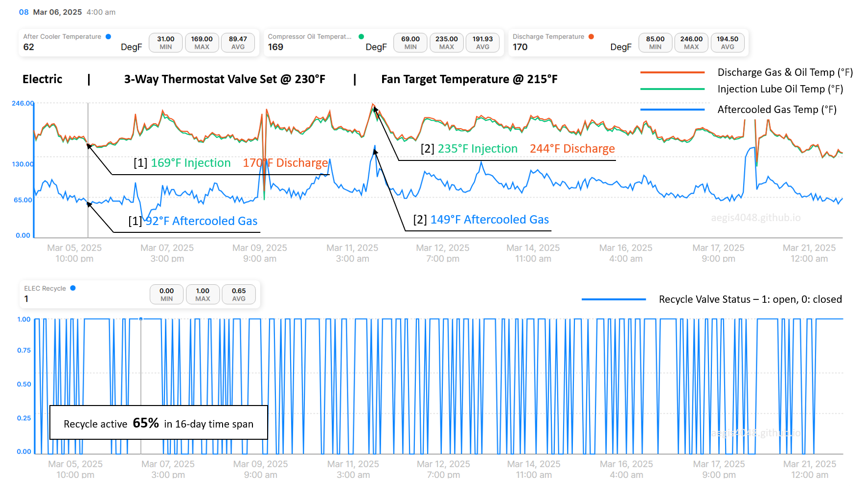
Figre 64: Example telemetry data of an electric compressor, with the same 230°F thermostat setpoint and 215°F aftercooled target temperature as in Figure 63. The difference is that this unit had recycle mode active for 65% of the time over the 16-day time span. Recycle mode was unable to generate sufficient heat of compression to keep the unit hot above the 215°F target. The unit recorded a lube oil temperature of 169°F at night around 4:00 AM [1], far below the 215°F target. Overall, the unit averaged 191.93°F lube oil temperature during the 16-day period, still below the desired 215°F. Although the unit occasionally reached temperatures near the 230°F thermostat setpoint, as seen in [2], it mostly stayed around 191.93°F, increasing the risk of lube oil contamination. For this specific unit, discharge pressure was fairly low around 120 psig, which usually don't cause liquid condensation at 191F for most gas compositions.
9.2. Gas engine models
BEFORE YOU READ: This section assumes reader familiarity with 3-way thermostatic valve operation (Section 7.4) and P&ID flow for electric model compressors (see Type D: Gas engine).
Note: For reader clarity, "discharge gas" refers to gases leaving the compression chamber, while "aftercooled gas" refers to gases leaving the fan. The hot discharge gas is cooled inside the fan and exits the skid as cold aftercooled gas.
Gas engine models use a single shared engine driver to power both the compressor and the fan. The PLC manages engine combustion to control compressor RPM, meaning compressor speed is prioritized and the fan simply follows compressor RPM. When the compressor runs at full speed, the fan also runs at full speed; when the compressor slows down, the fan slows down accordingly.
Unlike electric models—where heat of compression is the only significant heat source—gas engine models generate additional heat from fuel gas combustion. As a result, gas engines run hotter than electric models, creating challenges during hot summer seasons due to the lack of independent fan RPM control. Overall, gas engine models have inferior temperature management compared to electric models.
Because of these limitations (plus emission concerns), electrics are preferred over gas engines by most operators, except for sites that lack access to power.
This section explains key characteristics of gas engine compressors:
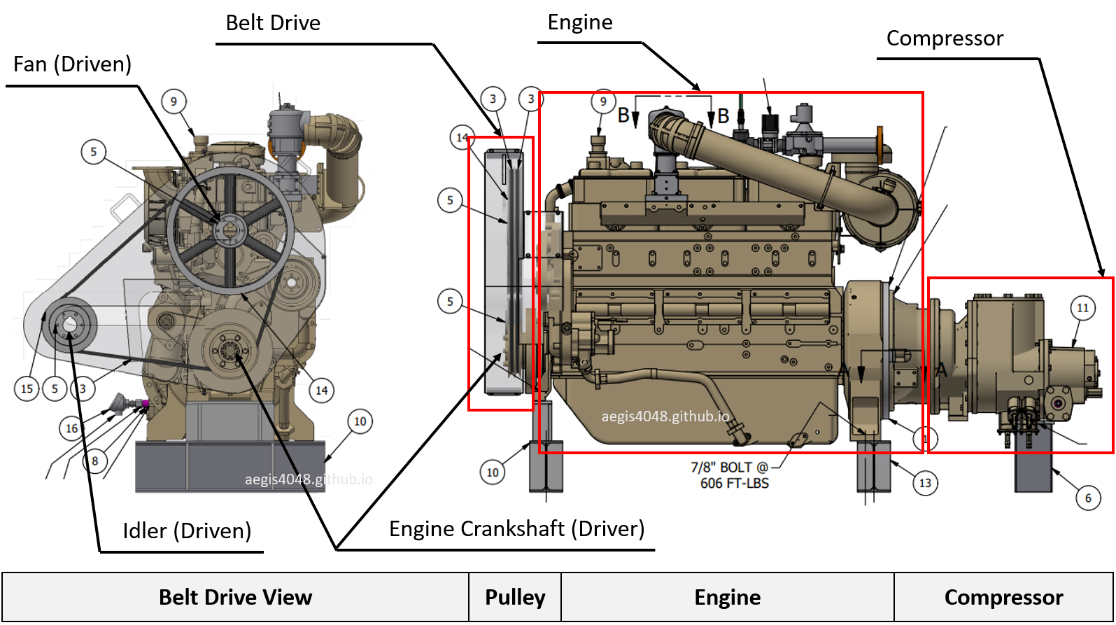
Figre 65: 3D drawing showing a belt drive pulley assembly, gas engine, and compressor. The engine crankshaft at the lower side of the engine extends left toward the fan side and right toward the compressor side. For the fan, the engine shaft (driver) spins the pulleys—one idler pulley and one fan pulley. The spinning fan pulley drives the fan. For the compressor, in gear-driven models (Section 2.3), the engine shaft connects to the compressor shaft through timing gears, while in direct-driven models (Section 2.2), the compressor rotors are directly driven without timing gears. In the left diagram, the fan pulley is approximately twice the diameter of the engine pulley. Thus, if the engine spins at 900 RPM, the fan spins at about 450 RPM due to the 2:1 pulley ratio.
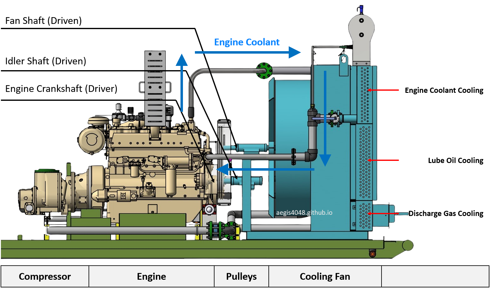
Figre 66: 3D drawing showing the connection between the engine driver and the fan. The compressor is driven by the engine shaft by timing gears. The cooling fan is driven by the engine through a belt drive pulley assembly.
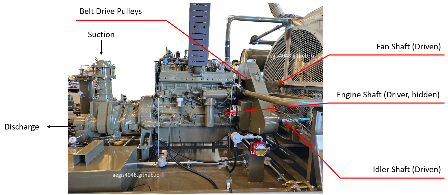
Figre 67: Real-life implementation of a gas engine compressor, corresponding to the drawings shown in Figure 65 and Figure 66, highlighting the engine driver pulley system.
Fuel Gas Combustion Heat
Gas engines burn fuel gas to generate power, spinning the engine crankshaft. This combustion heat becomes an additional source of temperature rise, on top of the heat of compression. As a result, gas engine models are generally free from low temperature issues that can trigger lube oil contamination. However, they face the opposite problem: high temperatures. Unlike electric models, gas engines lack independent RPM control on the fan, meaning the fan speed is tied directly to compressor speed. Combined with the extra heat from combustion—which electric models do not have—this makes temperature management even more difficult for gas engines compared to the electrics.
Unable to Control Fan RPM
Engine-driven models lack a dedicated fan driver because the compressor and fan must share a single engine. Sites using engine models typically have no access to external power, making it impractical to install a separate fan motor. Adding a second engine is also not feasible due to size, cost, and skid space limitations.
The engine crankshaft extends in both directions. As shown in Figure 66, the left side drives the compressor rotors—either direct-driven (Section 2.2) or gear-driven (Section 2.3)—while the right side drives the cooling fan through a belt-driven pulley assembly.
This pulley assembly works similarly to the timing gears used for compressor rotors. As shown in Figure 65, assume the pulley attached to the engine crankshaft (driver) has a 1-foot diameter, while the fan pulley (driven) has a 2-foot diameter. Based on the pulley ratio, if the engine turns at 1000 RPM, the fan will turn at 500 RPM. The pulley diameter ratio directly sets the fixed speed ratio between the engine shaft and the fan, just as gear ratios determine rotor speed in the compressor.
Still, no real-time fan RPM adjustment is possible. When the compressor operates at full speed, the fan does too, potentially causing overcooling. When the compressor slows down, the fan also slows, increasing the risk of undercooling. In practice, undercooling is more common, as the additional heat from fuel combustion overwhelms the fan's maximum cooling capacity, especially during hot summer days. This inability to independently control fan speed is a key reason why electric-driven models offer superior temperature management compared to gas engine models.
High Temperature Problems During Recycle
(see Section 8.3 for recycle mode explanations)
In electric compressor models (see Section 9.1), recycle mode often leads to low temperature problems due to limited heat of compression. Engine-driven models face the opposite issue: high temperatures during recycle. While the heat of compression is still reduced under low-flow conditions, the heat generated from continuous fuel gas combustion remains significant.
This becomes particularly problematic because fan RPM is directly tied to compressor RPM. When recycle mode slows the compressor, fan speed also drops, reducing cooling capacity. This is because the compressor and the fan shared the same engine crankshaft driver. However, combustion continues producing heat, sometimes overwhelming the cooler’s reduced capacity. Unlike electric models, engine-driven systems must manage both compression and combustion heat sources without fan RPM control capability, making thermal control more complex.
To mitigate this, the fan must be sized to handle peak heat loads even at minimum operating speeds. For example, if recycle mode maintains minimum compressor speed at 900 RPM and the pulley ratio to the fan is 2:1 (pulley structure shown in Figure 65), the fan operates at 450 RPM. If the maximum compressor RPM is 2400 RPM, the corresponding fan RPM would be 1200 RPM. The cooling system must be capable of removing sufficient thermal load at the reduced 450 RPM during recycle, without excessive overcooling at 1200 RPM during full-speed operation. Proper cooling fan sizing by compressor packagers is essential to maintain thermal stability across the full operating range.
While most gas engine applications don't see any problems, some installations struggle with temperature management during hot summer days.
Reliance On Thermostat Valve
The 3-way thermostat valve (example shown in Figure 27) is the only available real-time temperature control for engine-driven compressor models. Fan sizing and pulley ratios are fixed at installation and cannot respond to real-time temperature fluctuations.
The 3-way thermostat valve contains an expanding/contracting element that automatically adjusts its internal mixing position to maintain lube oil temperature near a target setpoint (e.g., 230°F). However, as explained in Section 7.4, the thermostat valve fails to maintain temperature under two scenarios: [1] if the incoming hot oil bypassing the fan (B-port) is already below 230°F, or [2] if the cooled oil exiting the fan (C-port) remains above 230°F because the cooler cannot remove enough heat. While scenario [1] is rare for engine models due to abundant combustion heat, scenario [2] can occur during hot summer days, especially during recycle mode when fan RPM is reduced and cooling capacity drops. Fan RPM reduces because the fan shares the same engine driver used for compressor rotors, and the PLC prioritizes rotor RPM. This lack of independent fan control is a key reason why electric-driven compressor models offer superior temperature management compared to engine-driven models.
It is important to note that the thermostat valve controls only the lube oil temperature. Aftercooled gas temperature is not regulated and floats with ambient conditions. I personally do not have any telemetry data showing aftercooled gas temperature fluctuations for engine models, because temperature transmitters are typically not installed on the aftercooled gas line—there is no purpose in monitoring a parameter that cannot be actively controlled. However, the floating behavior would likely resemble the trend shown in Figure 63, with aftercooled gas temperature rising during the day and falling at night, following ambient air temperature cycles.
Engine Coolant
(See Figure 18 for an example engine model P&ID.)
The engine coolant system cools the gas engine and is routed through a dedicated section of the fan, as shown in Figure 60. The coolant temperature is another critical variable that must be maintained within an acceptable range. However, similar to the aftercooled gas line, there is no thermostat valve installed on the coolant line. As a result, the coolant temperature cannot be actively controlled and floats based on ambient conditions, engine load, and compressor RPM.
Figure 68 below shows a temperature trend for discharge gas/lube oil, and engine coolant. While the discharge side temperature is regulated around the 230°F thermostat setpoint, the coolant temperature fluctuates throughout the day. This floating behavior introduces another layer of complexity to temperature management in engine-driven compressor models, highlighting another temperature control advantage of electric models.
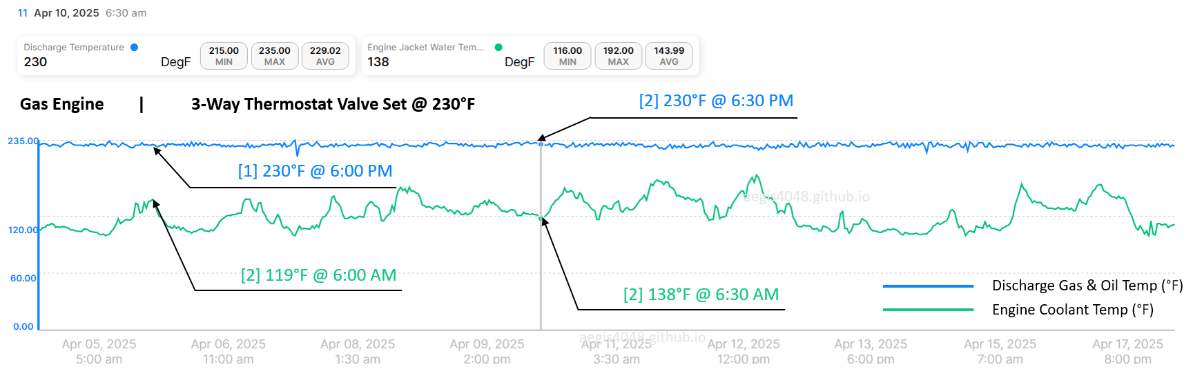
Figre 68: Example temperature telemetry data of a gas engine unit. The blue line shows the discharge-side lube oil and gas mixture exiting the compression chamber. The green line shows engine coolant temperature. The discharge-side temperature remains flat due to the presence of a thermostat valve maintaining 230°F, while the coolant temperature follows a sine wave pattern, driven by day/night ambient air temperature changes.
10. Lube oil contamination problems
Lube oil refill is the single largest maintenance cost in oil-flooded screw compressor operations. The FX12 compressor by Flogistix, shown in Figure 13, has a 20-gallon lube oil capacity, while the FX17 compressor in Figure 1 holds 60 gallons. Lube oil contamination leads to oil loss into the sales line and can trigger a low-level shutdown—detected by an electric liquid level switch installed on the discharge scrubber, as shown in Figure 33. Assuming polyglycol synthetic oil priced at $60 per gallon, a low oil level shutdown would cost an operator $1,200 to refill the FX12 compressor (20 × 60), and $3,600 for the FX17 compressor (60 × 60).
As explained in Section 1.3, lube oil serves three critical functions:
[1] Provides sealing between the two helical rotors, which are designed to avoid direct contact (see Section 2.1)
[2] Lubricates moving parts, reducing friction and wear
[3] Absorbs and dissipates heat
Screw compressors often experience process gas condensation inside the compression chamber. This condensed liquid mixes with the lube oil, diluting it and reducing its viscosity. Reduced viscosity leads to three major problems:
[1] Inadequate lubrication, which can cause damage to compressor bearings. Each compressor model has a minimum manufacturer viscosity specification that must be met to ensure proper operation.
[2] Lube oil foaming occurs when gas becomes entrained in the oil, reducing its lubricity. Bearings and rotors require a continuous pressurized oil film, which foam cannot provide—leading to increased wear and risk of mechanical failure. Foaming can also appear as “oil loss,” even though the total oil mass remains unchanged; the oil is simply aerated. Lube oils come with de-foamer additives for this reason.
[3] Reduced capture efficiency of the coalescer in the discharge scrubber (V-300), shown in Figure 15. The scrubber acts as a two-phase separator, capturing most of the lube oil from the compressed gas. While about 97% of oil separates by gravity, the remaining 3% exists as mist and is captured by a coalescer at the top. Lower viscosity makes the 3% mist oil harder to capture by the coalescer, allowing more to escape with the gas stream, resulting in oil loss into the sales line. This requires more frequent and costly oil refills.
Lube oil contamination from condensed liquid mixing can be avoided by operating the compressor at a temperature sufficiently above the dew point of the process gas. A general rule is to maintain 15–20°F above the dew point, with 30°F as the ideal buffer. In practice, oil-flooded screw compressors are intentionally designed to operate as hot as possible—typically 20–30°F below the maximum allowable temperature of 250°F (depends on manufacturers). This is why thermostat valve setpoints (see Section 7.4) are commonly set at 230°F, providing a 20°F safety margin below the high temperature shutdown threshold.
In other words, if the calculated dew point temperature of the process gas at a given discharge pressure exceeds 200°F, you begin to risk condensation—assuming a 230°F thermostat setpoint—because the operating temperature may no longer maintain sufficient buffer above the dew point.
The lube oil contamination problems tends to be problems for the following five scenarios:
If you prefer a quick takeaway: run a dew point check if your system handles gas above 2000 Btu/scf or has an inlet temperature over 110°F. Higher Btu values correlate with higher dew point temperatures. Similarly, inlet temperatures above 110°F increase water vapor saturation, which also raises the dew point. When acquiring a gas sample, specifically request the lab to include water fractions, as most standard lab reports include water contents. Absence of exact water fraction number will force you to assume maximum water saturation to prepare for the worst-case scenario which may over-predict dew point temperature and falsely rule out oil-flooded screw compressor options.
10.1. Frequent shutdown/autostart units
A compressor keeps the unit hot only while running—either during normal operation or recycle mode. Electric units rely solely on heat of compression, while engine units also gain heat from combustion. Once shut down, the unit cools to ambient temperature (40–120°F, depending on region and time of the season). After a prolonged shutdown, startup begins cold and may take 0.5–3 hours to reach full temperature. During this warm-up, internal temperatures may stay below the dew point, causing condensation that mixes with and contaminates lube oil. Although recycle mode exists to avoid shutdown, units with poor recycle control may still experience frequent shutdowns, causing repeated cold auto-starts and ongoing oil contamination.
Figure 57 shows a case in which a unit experienced a 12-hour shutdown. When the compressor restarted at 12:49 PM, the lube oil temperature was near ambient at 65°F. It took 35 minutes to reach 182°F (by 1:24 PM) [1], and another 247 minutes to stabilize at 233°F by 5:31 PM [2]. During this extended warm-up, internal temperatures likely remained below the gas dew point for several hours, allowing condensation to form and mix with the lube oil. During the first heating period in [1], contamination was almost certain—the initial 65°F is far too low to prevent condensation for any compression scenarios.
Although recycle mode is designed to keep the compressor running at low load to avoid shutdowns, poor recycle control can lead to frequent shutdowns and auto-starts. These cold auto-starts increase the risk of lube oil contamination due to repeated condensation events, ultimately accelerating oil degradation and loss.
10.2. Oversized electric units
Oversized electric compressors frequently enter recycle mode due to insufficient gas volume. During recycle, rotor RPM drops to the minimum sustainable level (shown in Figure 45), generating minimal heat of compression. If recycle mode accounts for less than 10–20% of total run time, the unit may retain sufficient heat. But when recycle dominates—e.g., 60% of run time—the unit may run too cold to stay above a dew point temperature.
Good trend: In Figure 63, the lube oil temperature remains stable near the 215°F fan setpoint due to minimal recycle.
Bad trend: In Figure 64, recycle mode was active 65% of the time over 16 days. As a result, the unit couldn’t sustain heat, dropping as low as 169°F at night and averaging just 194.5°F—well below 215°F target fan setpoint.
Oversizing often occurs 6–9 months after installation, as natural well decline reduces gas volume at the compressor. A unit that was initially right-sized becomes oversized over time. Timely downsizing helps avoid low-temperature recycle issues and reduces rental costs, but is often delayed since VRUs are not a primary operational focus (I wrote an article on this topic: Predicting VRU Economics/Downsizing Timing For Declining Wells). That said, as long as the unit remains above the dew point, it may still be acceptable from a lube oil maintenance standpoint.
10.3. High discharge pressure vapor recovery
Dew point temperature increases with increasing pressure. Figure 69 shows the phase envelope of a 2500 Btu/scf vapor sample taken from an atmospheric tank vapor recovery. Figure 70 shows a zoomed-in version of the same envelope, truncated at 400 psig on the y-axis, noting that typical screw compressor discharge pressure limits are at 350 psig. The operating condition (T, P) at the discharge side must stay in the gas phase region to avoid forming liquid.
The below summarizes dew point temperatures reading from Figure 70:
100 psig discharge P → 182°F dew point T
150 psig discharge P → 202°F dew point T
200 psig discharge P → 218°F dew point T
250 psig discharge P → 230°F dew point T
300 psig discharge P → 241°F dew point T
With a 230°F thermostat valve setpoint (which defines the compressor's operating temperature—see Section 7.4), condensation risk begins around 150 psig, where the dew point reaches 202°F. Since a 15–20°F margin above dew point is recommended—and 30°F is ideal—this provides only a narrow buffer. At 200 psig, the dew point is 218°F, reducing the margin to 12°F. By 250 psig, dew point equals the setpoint, eliminating the margin and guaranteeing lube oil contamination.
If the salesline requirement for this tank vapor recovery application is below 150–180 psig, oil-flooded screw compressors remain suitable. For higher line pressures, rotary vane compressors—which do not suffer from lube oil contamination—should be considered, though they are typically more expensive than screws.
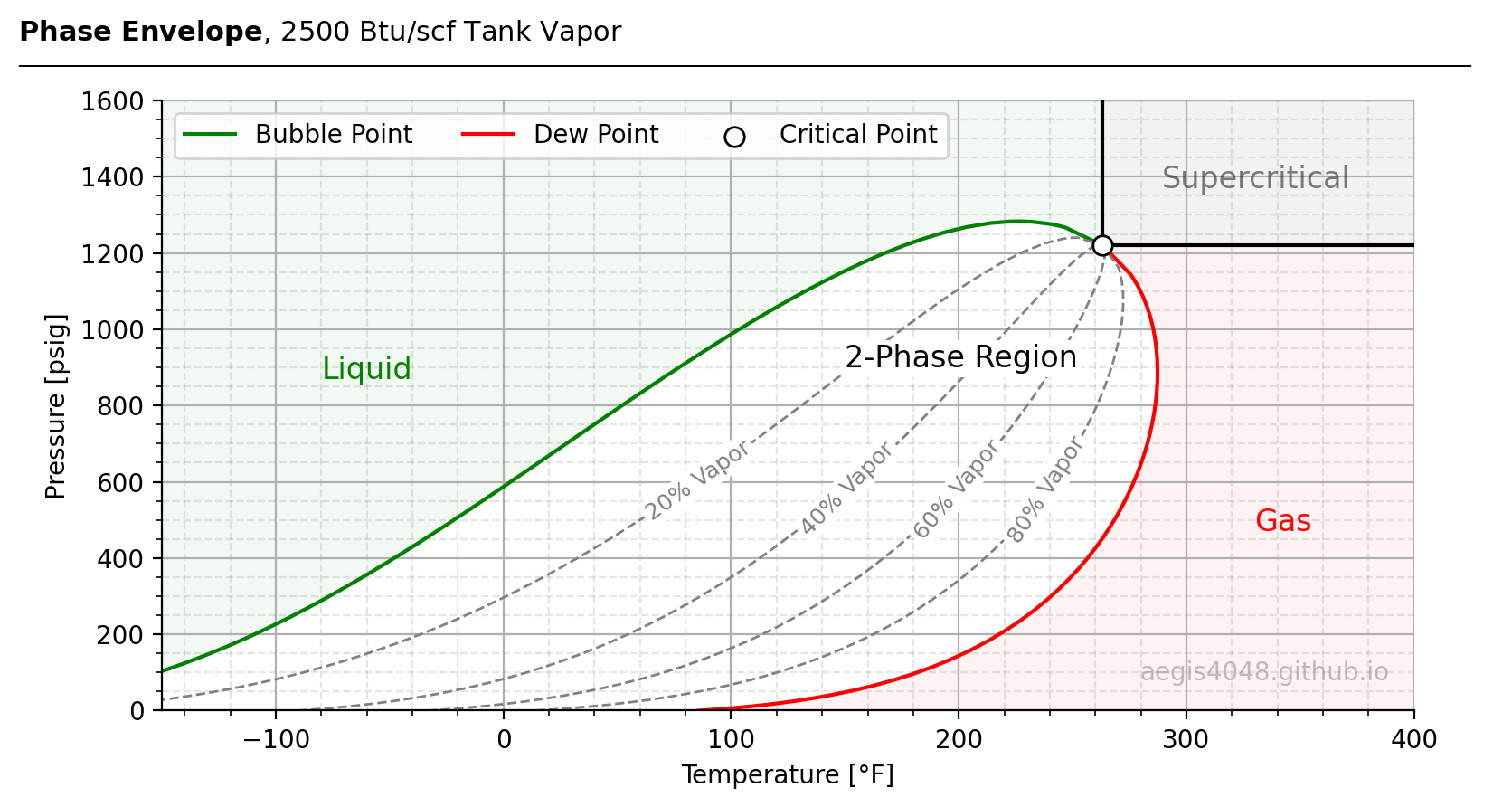
Figre 69: Phase envelope of a hydrocarbon mixture compound. Sample is an upstream wellsite tank vapor with 2500 Btu/scf energy content. Simulated in BR&E Promax, and plotted in Python.
Source Code For Figure (69)
import pandas as pd
import numpy as np
import matplotlib.pyplot as plt
from matplotlib.patches import Polygon

file = 'https://aegis4048.github.io/downloads/notebooks/sample_data/screw_compressor_article.xlsx'
dfs = [pd.read_excel(file, sheet_name=f'{n}% Vapor') for n in range(0, 101, 10)]

fig, ax = plt.subplots(figsize=(8, 4.5))

t_crit = 263.1727464076
p_crit = 1219.74099087

ax.plot(dfs[0]['Temperature'], dfs[0]['Pressure'], label='Bubble Point', color='green')
ax.plot(dfs[10]['Temperature'], dfs[10]['Pressure'], label='Dew Point', color='red')
ax.scatter(t_crit, p_crit, s=60, edgecolor='k', fc='white', zorder=3, label='Critical Point')

angles = [35, 45, 50, 57]
for i, label, angle in zip([2, 4, 6, 8], ['20% Vapor', '40% Vapor', '60% Vapor', '80% Vapor'], angles):
    T = dfs[i]['Temperature'].values
    P = dfs[i]['Pressure'].values

    dT = np.diff(T)
    dP = np.diff(P)
    seg_lengths = np.sqrt(dT**2 + dP**2)
    cumulative = np.insert(np.cumsum(seg_lengths), 0, 0)
    total_len = cumulative[-1]

    half_len = total_len / 2
    idx = np.searchsorted(cumulative, half_len) - 1
    frac = (half_len - cumulative[idx]) / seg_lengths[idx]

    t_mid = T[idx] + frac * (T[idx + 1] - T[idx])
    p_mid = P[idx] + frac * (P[idx + 1] - P[idx])

    ax.plot(T, P, color='grey', ls='--', lw=1, alpha=0.99)
    ax.text(t_mid, p_mid, label, fontsize=9, rotation=angle,
            ha='center', va='center', color='grey',
            bbox=dict(facecolor='white', edgecolor='none', pad=1.5, alpha=1))


ax.set_ylim(0, 1600)
ax.set_xlim(-150, 400)
x_min, x_max = ax.get_xlim()
y_max = ax.get_ylim()[1]

# Supercritical region
ax.plot([t_crit, t_crit], [p_crit, y_max], color='black')
ax.plot([t_crit, x_max], [p_crit, p_crit], color='black')
ax.fill_between([t_crit, x_max], p_crit, y_max, color='black', alpha=0.05, zorder=0)
ax.text(289, 1370, 'Supercritical', fontsize=12, ha='left', color='black', alpha=0.5)

# Gas region
T = dfs[10]['Temperature']
P = dfs[10]['Pressure']
t_interp = np.interp(p_crit, P, T)
verts = [(t, p) for t, p in zip(T, P) if p <= p_crit]
verts += [(t_interp, p_crit), (x_max, p_crit), (x_max, P.min()), (T.iloc[0], P.iloc[0])]
ax.add_patch(Polygon(verts, closed=True, color='red', alpha=0.05, zorder=0))
ax.text(330, 470, 'Gas', fontsize=12, ha='left', color='red', alpha=0.99)

# Liquid region
T = dfs[0]['Temperature']
P = dfs[0]['Pressure']
mask = T <= t_crit
T_sel, P_sel = T[mask], P[mask]
verts = [(x_min, y_max), (x_min, P_sel.iloc[0])] + list(zip(T_sel, P_sel)) + [(T_sel.iloc[-1], y_max)]
ax.add_patch(Polygon(verts, closed=True, color='green', alpha=0.05, zorder=0))
ax.text(-80, 870, 'Liquid', fontsize=12, ha='left', color='green', alpha=0.99)

ax.text(150, 900, '2-Phase Region', fontsize=12, ha='left', color='black', alpha=0.99,
       bbox=dict(facecolor='white', edgecolor='none', pad=1.5, alpha=1))

ax.set_xlabel('Temperature [°F]')
ax.set_ylabel('Pressure [psig]')
ax.grid(True)
ax.minorticks_on()
ax.grid(axis='both', which='minor', color='grey', linestyle='--', alpha=0.2)
ax.spines['top'].set_visible(False)
ax.spines['right'].set_visible(False)

handles, labels = ax.get_legend_handles_labels()
ax.legend(handles, labels, ncol=3)

ax.text(0.98, 0.05, 'aegis4048.github.io', fontsize=10, ha='right', transform=ax.transAxes, color='grey', alpha=0.5)

def setbold(txt): return ' '.join([r"$\bf{" + item + "}$" for item in txt.split(' ')])
fig.suptitle(setbold('Phase Envelope') + ', 2500 Btu/scf Tank Vapor', verticalalignment='top',
             x=0, horizontalalignment='left', fontsize=11)
yloc = 0.9
ax.annotate('', xy=(0.01, yloc + 0.01), xycoords='figure fraction',
            xytext=(1.02, yloc + 0.01), arrowprops=dict(arrowstyle="-", color='k', lw=0.7))

fig.tight_layout()
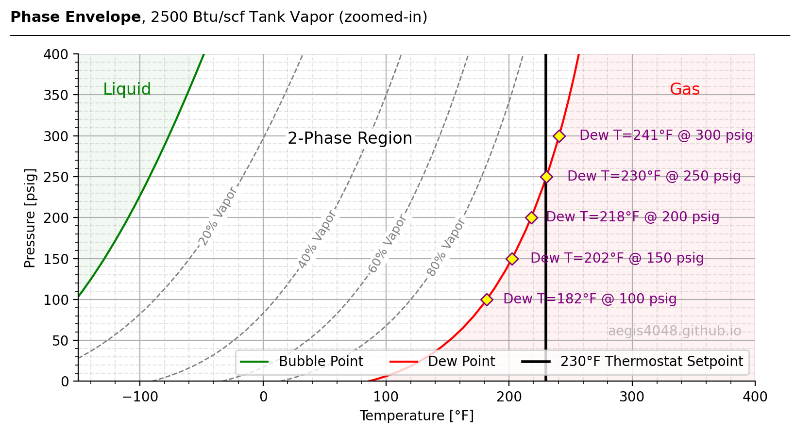
Figre 70: Zoomed-in version of Figure 69. Simulated in BR&E Promax, and plotted in Python. Oil-flooded screw compressors typically reach up to 350 psig. The plot shows dew point temperatures at various pressures. As pressure increases, dew point temperature rises. With a 230°F thermostat setpoint and a recommended 30°F buffer, condensation risk begins above 150 psig.
Source Code For Figure (70)
import pandas as pd
import numpy as np
import matplotlib.pyplot as plt
from matplotlib.patches import Polygon

file = 'https://aegis4048.github.io/downloads/notebooks/sample_data/screw_compressor_article.xlsx'
dfs = [pd.read_excel(file, sheet_name=f'{n}% Vapor') for n in range(0, 101, 10)]

fig, ax = plt.subplots(figsize=(8, 4.5))

t_crit = 263.1727464076
p_crit = 1219.74099087

ax.plot(dfs[0]['Temperature'], dfs[0]['Pressure'], label='Bubble Point', color='green')
ax.plot(dfs[10]['Temperature'], dfs[10]['Pressure'], label='Dew Point', color='red')

ax.set_ylim(0, 400)
ax.set_xlim(-150, 400)
x_min, x_max = ax.get_xlim()
y_min, y_max = ax.get_ylim()

angles = [60, 60, 60, 60]
for i, label, angle in zip([2, 4, 6, 8], ['20% Vapor', '40% Vapor', '60% Vapor', '80% Vapor'], angles):
    T = dfs[i]['Temperature'].values
    P = dfs[i]['Pressure'].values

    # Clip to plotting bounds
    mask = (T >= x_min) & (T <= x_max) & (P >= y_min) & (P <= y_max)
    T_clipped = T[mask]
    P_clipped = P[mask]

    if len(T_clipped) < 2:
        continue  # Skip if not enough points to compute a midpoint

    dT = np.diff(T_clipped)
    dP = np.diff(P_clipped)
    seg_lengths = np.sqrt(dT**2 + dP**2)
    cumulative = np.insert(np.cumsum(seg_lengths), 0, 0)
    total_len = cumulative[-1]

    half_len = total_len / 2
    idx = np.searchsorted(cumulative, half_len) - 1
    frac = (half_len - cumulative[idx]) / seg_lengths[idx]

    t_mid = T_clipped[idx] + frac * (T_clipped[idx + 1] - T_clipped[idx])
    p_mid = P_clipped[idx] + frac * (P_clipped[idx + 1] - P_clipped[idx])

    ax.plot(T, P, color='grey', ls='--', lw=1, alpha=0.99)
    ax.text(t_mid, p_mid, label, fontsize=9, rotation=angle,
            ha='center', va='center', color='grey',
            bbox=dict(facecolor='white', edgecolor='none', pad=1.5, alpha=1))

# Gas region
T = dfs[10]['Temperature']
P = dfs[10]['Pressure']
t_interp = np.interp(p_crit, P, T)
verts = [(t, p) for t, p in zip(T, P) if p <= p_crit]
verts += [(t_interp, p_crit), (x_max, p_crit), (x_max, P.min()), (T.iloc[0], P.iloc[0])]
ax.add_patch(Polygon(verts, closed=True, color='red', alpha=0.05, zorder=0))
ax.text(330, 350, 'Gas', fontsize=12, ha='left', color='red', alpha=0.99)

# Liquid region
T = dfs[0]['Temperature']
P = dfs[0]['Pressure']
mask = T <= t_crit
T_sel, P_sel = T[mask], P[mask]
verts = [(x_min, y_max), (x_min, P_sel.iloc[0])] + list(zip(T_sel, P_sel)) + [(T_sel.iloc[-1], y_max)]
ax.add_patch(Polygon(verts, closed=True, color='green', alpha=0.05, zorder=0))
ax.text(-130, 350, 'Liquid', fontsize=12, ha='left', color='green', alpha=0.99)

ax.text(20, 290, '2-Phase Region', fontsize=12, ha='left', color='black', alpha=0.99,
       bbox=dict(facecolor='white', edgecolor='none', pad=1.5, alpha=1))

ax.set_xlabel('Temperature [°F]')
ax.set_ylabel('Pressure [psig]')
ax.grid(True)
ax.minorticks_on()
ax.grid(axis='both', which='minor', color='grey', linestyle='--', alpha=0.2)
ax.spines['top'].set_visible(False)
ax.spines['right'].set_visible(False)

ax.axvline(x=230, color='k', linestyle='-', linewidth=2, label='230°F Thermostat Setpoint')

handles, labels = ax.get_legend_handles_labels()
ax.legend(handles, labels, ncol=3, loc='lower right')


ax.scatter(181.8355342547, 100, marker='D', s=40, fc='yellow', edgecolor='purple', zorder=10)
ax.text(195, 100, 'Dew T=182°F @ 100 psig', fontsize=10, ha='left', va='center', color='purple')

ax.scatter(202.3073722246, 150, marker='D', s=40, fc='yellow', edgecolor='purple', zorder=10)
ax.text(217, 150, 'Dew T=202°F @ 150 psig', fontsize=10, ha='left', va='center', color='purple')

ax.scatter(217.8299782129, 200, marker='D', s=40, fc='yellow', edgecolor='purple', zorder=10)
ax.text(230, 200, 'Dew T=218°F @ 200 psig', fontsize=10, ha='left', va='center', color='purple')

ax.scatter(230.2676365518, 250, marker='D', s=40, fc='yellow', edgecolor='purple', zorder=10)
ax.text(247, 250, 'Dew T=230°F @ 250 psig', fontsize=10, ha='left', va='center', color='purple')

ax.scatter(240.5520855614, 300, marker='D', s=40, fc='yellow', edgecolor='purple', zorder=10)
ax.text(257, 300, 'Dew T=241°F @ 300 psig', fontsize=10, ha='left', va='center', color='purple')

ax.text(0.98, 0.14, 'aegis4048.github.io', fontsize=10, ha='right', transform=ax.transAxes, color='grey', alpha=0.5)

def setbold(txt): return ' '.join([r"$\bf{" + item + "}$" for item in txt.split(' ')])
fig.suptitle(setbold('Phase Envelope') + ', 2500 Btu/scf Tank Vapor (zoomed-in)', verticalalignment='top',
             x=0, horizontalalignment='left', fontsize=11)
yloc = 0.9
ax.annotate('', xy=(0.01, yloc + 0.01), xycoords='figure fraction',
            xytext=(1.02, yloc + 0.01), arrowprops=dict(arrowstyle="-", color='k', lw=0.7))

fig.tight_layout()
10.4. High BTU vapor recovery (above 2000 Btu)
Dew point temperature increases with high heating value (Btu/scf). Lube oil contamination problems tend to be a challenge for high-BTU applications above 2000 Btu/scf. These are usually low pressure vapor recovery applications for either VRTs operating 1-5 psig, or tanks operating below 1 psig. The issue arises because higher-BTU gases exhibit higher dew point temperatures at a given pressure, increasing the risk of process gas condensation into liquid during compression.
Figure 71 shows phase envelopes for three representative gas samples: 2000, 2500, and 3000 Btu/scf. These values reflect realistic Btu values frequently observed for VRT and tank vapor recovery systems. As Btu content increases, the phase envelope shifts rightward—indicating higher dew point temperatures at equal pressures. This means that as samples get richer (high Btu), compressors must operate at higher temperatures to stay in the gas region.
The three intersection points on the 200 psig isobar represent dew point temperatures for each sample:
2000 Btu/scf → 172°F dew point T @200# discharge
2500 Btu/scf → 218°F dew point T @200# discharge
3000 Btu/scf → 249°F dew point T @200# discharge
The vertical line at 230°F reflects the typical thermostat valve setpoint for oil-flooded screw compressors, which maintains the normal operating temperature of the unit (see Section 7.4). At 200 psig, both the 2000 and 2500 Btu/scf gases remain below this threshold, though the 2500 Btu/scf sample approaches the limit with minimal safety margin of only 12° (you want at least 15-30°F margin). In contrast, the dew point temperature for the 3000 Btu/scf gas 249°F exceeds the 230°F setpoint, guaranteeing condensation and subsequent lube oil contamination.
For this reason, screw compressors are not feasible for this 3000 Btu/scf gas at 200 psig discharge (potentially not feasible for 2500 Btu/scf gas as well due to minimal operating temperature margin, only 12°F). Alternatives like rotary vane compressors—which do not rely on lube oil—should be considered. While more expensive, rotary vanes are better suited for high-BTU recovery. The 2000 Btu/scf gas, however, provides enough margin to safely operate within the gas region across the full pressure range of typical screw compressors (60–350 psig).
It's important to note that phase envelopes can vary significantly between gas samples, even if they have similar Btu/scf values. For example, while the 2500 Btu/scf sample discussed here shows a 218°F dew point at 200 psig, another sample with the same energy content and discharge pressure could show a much lower dew point—such as 180°F. I’ve observed this firsthand in the field on multiple occasions. Very common.
In general, if your application is above 2000 Btu/scf, it is highly recommended to run a dew point check when considering an oil-flooded screw compressor installation. You can send me a business inquiry if you would like me to run a dew point check.
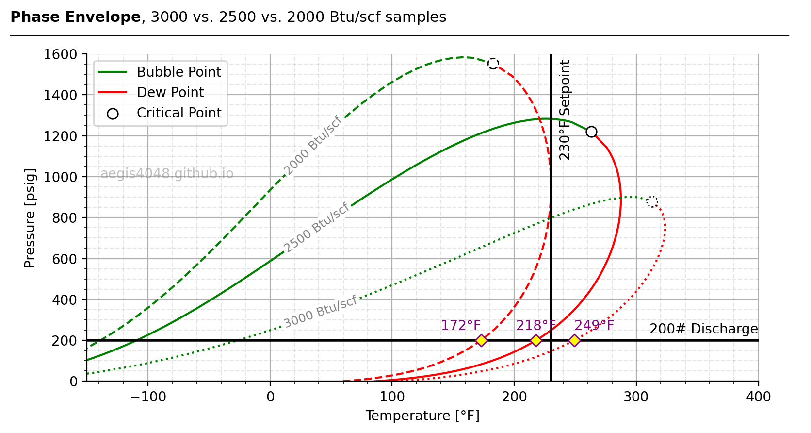
Figre 71: Phase envelopes of various natural gas sample at different energy contents (Btu/scf). Simulated in BR&E Promax, and plotted in Python. The Btu/scf samples have higher dew point temperatures at the same 200# discharge pressure. The 230°F vertical line represents the typical 230°F setpoint for a 3-way thermostat valve that determines the normal operating temperature of an oil-flooded screw compressor. The dew point must be below this 230°F limit to avoid condensation and subsequent lube oil contamination issues. The horizonal isobar line represents a fixed discharge pressure at 200 psig.
Source Code For Figure (71)
import pandas as pd
import numpy as np
import matplotlib.pyplot as plt
from matplotlib.patches import Polygon

file = 'https://aegis4048.github.io/downloads/notebooks/sample_data/screw_compressor_article.xlsx'
dfs = [pd.read_excel(file, sheet_name=f'{n}% Vapor') for n in range(0, 101, 10)]
dfs.append(pd.read_excel(file, sheet_name='2000 Btu Bubble'))
dfs.append(pd.read_excel(file, sheet_name='2000 Btu Dew'))
dfs.append(pd.read_excel(file, sheet_name='3000 Btu Bubble'))
dfs.append(pd.read_excel(file, sheet_name='3000 Btu Dew'))

fig, ax = plt.subplots(figsize=(8, 4.5))

t_crit1 = 263.1727464076 # 2500 Btu/scf
p_crit1 = 1219.74099087  # 2500 Btu/scf

t_crit2 = 182.7752706    # 2000 Btu/scf
p_crit2 = 1552.581899    # 2000 Btu/scf

t_crit3 = 312.9541125064 # 3000 Btu/scf
p_crit3 = 877.4475701297 # 3000 Btu/scf

ax.plot(dfs[0]['Temperature'], dfs[0]['Pressure'], label='Bubble Point', color='green')
ax.plot(dfs[10]['Temperature'], dfs[10]['Pressure'], label='Dew Point', color='red')
ax.scatter(t_crit1, p_crit1, s=60, edgecolor='k', fc='white', zorder=3, label='Critical Point')

ax.plot(dfs[11]['Temperature'], dfs[11]['Pressure'], color='green', ls='--')
ax.plot(dfs[12]['Temperature'], dfs[12]['Pressure'], color='red', ls='--')
ax.scatter(t_crit2, p_crit2, s=60, edgecolor='k', fc='white', zorder=3, ls='--')

ax.plot(dfs[13]['Temperature'], dfs[13]['Pressure'], color='green', ls='dotted')
ax.plot(dfs[14]['Temperature'], dfs[14]['Pressure'], color='red', ls='dotted')
ax.scatter(t_crit3, p_crit3, s=60, edgecolor='k', fc='white', zorder=3, ls='dotted')

ax.text(10, 1010, '2000 Btu/scf', fontsize=9, rotation=45, color='grey',
        bbox=dict(facecolor='white', edgecolor='none', pad=1.5, alpha=1))
ax.text(10, 630, '2500 Btu/scf', fontsize=9, rotation=35, color='grey',
        bbox=dict(facecolor='white', edgecolor='none', pad=1.5, alpha=1))
ax.text(10, 260, '3000 Btu/scf', fontsize=9, rotation=19, color='grey',
        bbox=dict(facecolor='white', edgecolor='none', pad=1.5, alpha=1))

ax.set_ylim(0, 1600)
ax.set_xlim(-150, 400)
x_min, x_max = ax.get_xlim()
y_max = ax.get_ylim()[1]

ax.set_xlabel('Temperature [°F]')
ax.set_ylabel('Pressure [psig]')
ax.grid(True)
ax.minorticks_on()
ax.grid(axis='both', which='minor', color='grey', linestyle='--', alpha=0.2)
ax.spines['top'].set_visible(False)
ax.spines['right'].set_visible(False)

handles, labels = ax.get_legend_handles_labels()
ax.legend(handles, labels, ncol=1, loc='upper left')

ax.axvline(x=230, color='k', linestyle='-', linewidth=2, label='230°F Thermostat Setpoint')
ax.text(237, 1080, '230°F Setpoint', rotation=90, va='bottom', ha='left', fontsize=10, color='black')

ax.axhline(y=200, color='k', linestyle='-', linewidth=2, label='230°F Thermostat Setpoint')
ax.text(400, 220, '200# Discharge', va='bottom', ha='right', fontsize=10, color='black')

ax.text(0.02, 0.62, 'aegis4048.github.io', fontsize=10, ha='left', transform=ax.transAxes, color='grey', alpha=0.5)

ax.scatter(249.0971642597, 200, marker='D', s=40, fc='yellow', edgecolor='purple', zorder=10)
ax.text(249.0971642597, 200 + 70, '249°F', fontsize=10, ha='left', va='center', color='purple')

ax.scatter(217.8299958163, 200, marker='D', s=40, fc='yellow', edgecolor='purple', zorder=10)
ax.text(217.8299958163, 200 + 70, '218°F', fontsize=10, ha='center', va='center', color='purple')

ax.scatter(172.7152181272, 200, marker='D', s=40, fc='yellow', edgecolor='purple', zorder=10)
ax.text(172.7152181272, 200 + 70, '172°F', fontsize=10, ha='right', va='center', color='purple')

def setbold(txt): return ' '.join([r"$\bf{" + item + "}$" for item in txt.split(' ')])
fig.suptitle(setbold('Phase Envelope') + ', 3000 vs. 2500 vs. 2000 Btu/scf samples', verticalalignment='top',
             x=0, horizontalalignment='left', fontsize=11)
yloc = 0.9
ax.annotate('', xy=(0.01, yloc + 0.01), xycoords='figure fraction',
            xytext=(1.02, yloc + 0.01), arrowprops=dict(arrowstyle="-", color='k', lw=0.7))

fig.tight_layout()
Phase envelopes are intended for two-phase systems. In oil and gas systems, water introduces a third phase because it is immiscible with hydrocarbons. Figure D demonstrates distortion on the dew point curve near the critical point due to the presence of liquid phase water. Adding just 2% water distorts the envelope. This effect is common in low suction pressure vapor recovery systems, which often have 0–8% water content depending on temperature.
The distortion becomes severe at the compressor discharge side (i.e., at elevated pressures) than the suction side, because the amount of water a gas stream can hold in vapor phase—i.e., saturated water—decreases with increasing pressure. Table 6 illustrates this: at 60°F inlet temperature, a gas stream can handle upto 1.75% mol frac water at 0 psig before dropping liquid-phase water, while at 50 psig, it can hold only 0.40% mol frac water.
In Figure D, the phase envelope was constructed assuming a constant 2% mol fraction water across all operating conditions (T, P). The following numbers are illustrative: at low pressure (e.g., 0 psig), a system might be able to hold 2–4% mol frac water in vapor phase without forming liquid. At high pressure (e.g., 500 psig), it might hold only about 0.2%. The excess water—e.g., 1.8% (2.0 − 0.2)—would condense as a separate immiscible water phase, creating a third phase and distorting the envelope, which is valid only for two-phase mixtures. While increasing temperature allows more water to remain in the vapor phase, rising pressure dominates and suppresses this capacity.
ProMax (the simulator used here) excludes water by default when constructing phase envelopes, which can lead to incorrect dew point readings if water is present. Fortunately, ProMax offers an alternate dew point calculation method that includes water. Do not rely on phase envelopes for dew points when water is present. Instead, use other dew point calculation tools that account for water content (in ProMax, "Vapor Pressure, Dew, Bubble Point" under "Add Analysis" supports this). If using a different simulator, confirm with your software vendor how water is handled in dew point calculations.
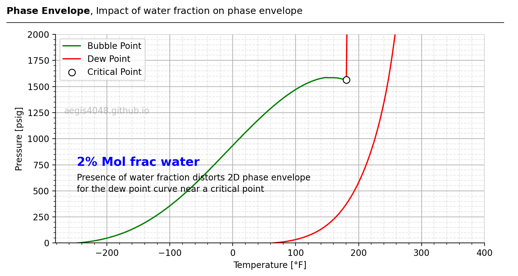
Figure D: Phase envelope of the same 2000 Btu/scf gas sample shown in Figure 71, with 2% saturated water added to reflect field conditions—where 0–8% water content is typical in low-pressure vapor recovery. The envelope shows distortion near the critical point on the dew point curve. This occurs because a 2D phase envelope assumes a two-phase system, which breaks down when water is present, as water is immiscible with hydrocarbons.
Source Code For The Figure (D)
import pandas as pd
import numpy as np
import matplotlib.pyplot as plt
from matplotlib.patches import Polygon

file = 'https://aegis4048.github.io/downloads/notebooks/sample_data/screw_compressor_article.xlsx'
dfs = []
dfs.append(pd.read_excel(file, sheet_name='2% Water Bubble'))
dfs.append(pd.read_excel(file, sheet_name='2% Water Dew'))


fig, ax = plt.subplots(figsize=(8, 4.5))


t_crit1 = 180.4400727908 # 2500 Btu/scf
p_crit1 = 1563.074498018  # 2500 Btu/scf


ax.plot(dfs[0]['Temperature'], dfs[0]['Pressure'], label='Bubble Point', color='green')
ax.plot(dfs[1]['Temperature'], dfs[1]['Pressure'], label='Dew Point', color='red')
ax.scatter(t_crit1, p_crit1, s=60, edgecolor='k', fc='white', zorder=3, label='Critical Point')


ax.set_ylim(0, 2000)
ax.set_xlim(None, 400)


ax.set_xlabel('Temperature [°F]')
ax.set_ylabel('Pressure [psig]')
ax.grid(True)
ax.minorticks_on()
ax.grid(axis='both', which='minor', color='grey', linestyle='--', alpha=0.2)
ax.spines['top'].set_visible(False)
ax.spines['right'].set_visible(False)


handles, labels = ax.get_legend_handles_labels()
ax.legend(handles, labels, ncol=1, loc='upper left')


ax.text(0.02, 0.62, 'aegis4048.github.io', fontsize=10, ha='left', transform=ax.transAxes, color='grey', alpha=0.5)


ax.text(0.05, 0.37, '2% Mol frac water', fontsize=14, ha='left', transform=ax.transAxes, color='blue', fontweight='bold')
ax.text(0.05, 0.3, 'Presence of water fraction distorts 2D phase envelope', fontsize=10, ha='left', transform=ax.transAxes, color='black')
ax.text(0.05, 0.245, 'for the dew point curve near a critical point', fontsize=10, ha='left', transform=ax.transAxes, color='black')


def setbold(txt): return ' '.join([r"$\bf{" + item + "}$" for item in txt.split(' ')])
fig.suptitle(setbold('Phase Envelope') + ', Impact of water fraction on phase envelope', verticalalignment='top',
             x=0, horizontalalignment='left', fontsize=11)
yloc = 0.9
ax.annotate('', xy=(0.01, yloc + 0.01), xycoords='figure fraction',
            xytext=(1.02, yloc + 0.01), arrowprops=dict(arrowstyle="-", color='k', lw=0.7))


fig.tight_layout()
10.5. High inlet temperature VRT/Tank vapor recovery (above 110F)
Dew point temperature increases with saturated water content, which itself rises with gas temperature. Saturated water refers to vapor-phase water—not liquid—but still present in the gas stream and capable of raising dew point.
In Table 5, dew point temperatures for the 2,000 Btu/scf gas sample (same one used in Figure 71) at 200 psig discharge pressure increase significantly with water content:
0% water mol frac → 172°F dew point T @200# discharge
5% water mol frac → 196°F dew point T @200# discharge
7% water mol frac → 212°F dew point T @200# discharge
10% water mol frac → 231°F dew point T @200# discharge
With 10% water, the dew point hits 231°F—above the 230°F thermostat setpoint for oil-flooded screw compressors. This contradicts my previous statement that "The 2,000 Btu/scf gas, however, provides enough margin to safely operate within the gas region across the full pressure range of typical screw compressors (60–350 psig)", which only holds true under dry 0% water conditions. In fact, 10% water lowers the heating value to 1,805 Btu/scf (simulation not shown) because water has no heating value.
This poses a critical risk: most lab gas analyses report dry samples unless water is specifically requested. Operators may unknowingly install compressors assuming 172°F dew point, only to face 231°F in reality. Once installed, condensation will cause lube oil contamination, adding $1,000-$3,000/month in refill costs on top of rental fees. Always request water fractions to be included in lab gas analysis.
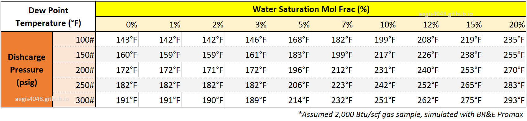
Table 5: Dew point temperature as a function of water mol fraction and discharge pressure, based on the same 2,000 Btu/scf gas stream used in Figure 71. Simulations were performed using BR&E ProMax, assuming saturated vapor at 150°F tank conditions. High tank temperature is used specifically to allow maximum water saturation as possible. A saturator block is used to artificially increase water saturation from the original sample.
Water content peaks in low-pressure, high-temperature systems, such as summer VRT/tank recovery or VRTs/tanks receiving gas from upstream heater treaters operating above 140°F. These tanks inherit the elevated temperatures of upstream heaters. Table 6 shows saturated water mol fractions across suction pressures from 0 to 50 psig, which reflect the full range of typical screw compressor suction limits.
The 3 psig row is highlighted here as it reflects typical VRT operating pressure:
70°F suction temperature → 2.06% mol frac water @ 3# suction
90°F suction temperature → 3.96% mol frac water @ 3# suction
110°F suction temperature → 7.23% mol frac water @ 3# suction
130°F suction temperature → 12.60% mol frac water @ 3# suction
150°F suction temperature → 21.10% mol frac water @ 3# suction
Above 110°F, water saturation starts to rise sharply. At 7.23% water and 200 psig discharge, the corresponding dew point—referencing Table 5—is approximately 212°F. That’s just 18°F below the 230°F thermostat setpoint, cutting into the 15–30°F safety buffer required to avoid condensation. If the inlet temperature reaches 130°F, water content can rise to 12.6%, pushing the dew point to around 240°F at 200 psig—completely ruling out the use of oil-flooded screw compressors, which cannot operate above 230°F.
In general, it is highly recommended to run dew point for VRT/tank vapor recovery, if inlet temperature exceeds 110F°.
Note that not all VRT/tank gas streams are fully saturated (heater and separator gas streams are fully saturated though), but assuming so provides a worst-case estimate. This may lead to conservative designs and over-elimination of screw compressors—but in absence of field-verified water data, it's a safer path. Of course, all this can be avoided if you can obtain lab analysis that reports water content.
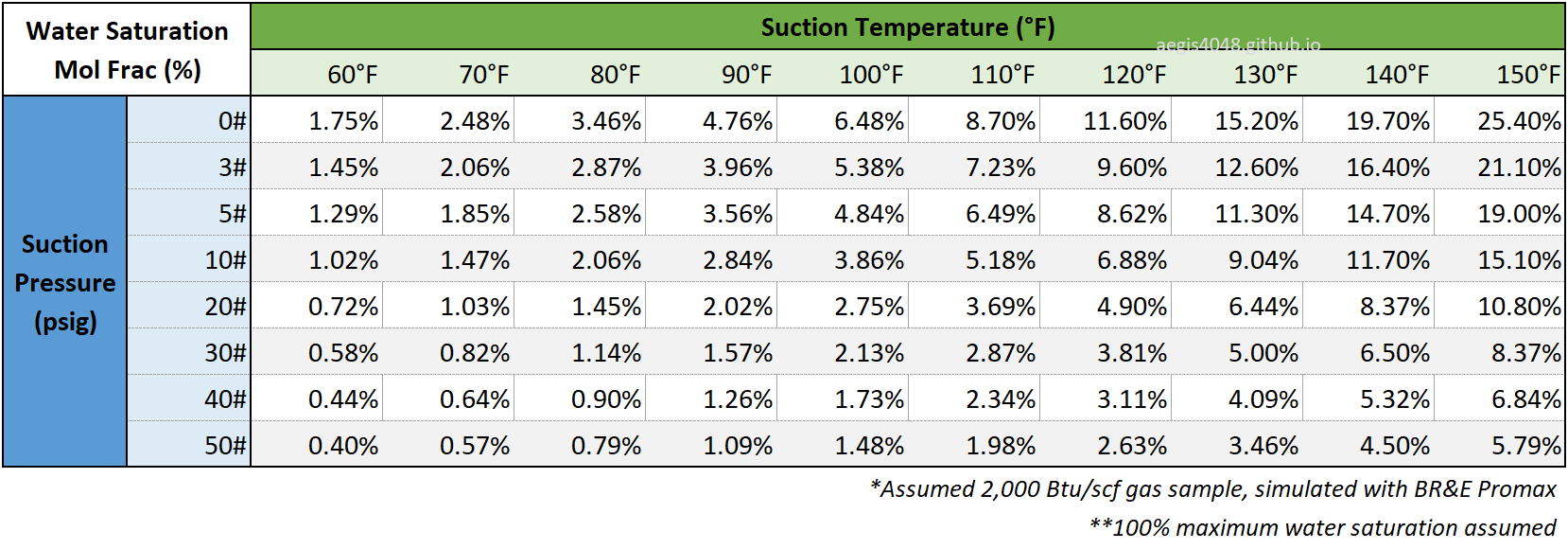
Table 6: Saturated water mol fraction as a function of suction temperature and suction pressure, based on the same 2,000 Btu/scf gas stream used in Figure 71. The water fraction sim results assume maximum 100% water saturation before dropping liquid.
11. Concluding Remarks
This is a long article—because there’s a lot to learn about oil-flooded screw compressors. I put real effort into including as much practical information as possible while keeping the content compact and clear. I don’t expect most readers to go through the entire piece from start to finish. Most will likely jump to specific sections using the table of contents sidebar.
If you did read the whole article in order, you may have noticed that I repeatedly reference the same sections and figures. That’s intentional. I assume readers will jump around and won’t absorb everything in one section—because many of these topics are interconnected. You need to understand one area to fully grasp another, so I wrote each section assuming the reader may not have full context from the others. Hopefully, that approach made it easier to navigate and understand.
The purpose of this article was to educate readers on how to operate an oil-flooded screw compressor from an operator’s point of view. It’s meant to help you understand how each control device works, how they regulate pressure and temperature, and how to interpret what you’re seeing on telemetry data. I wanted this to be a practical guide that helps you identify root causes when issues arise and understand how different configurations apply to different use cases. If you’ve read and understood the full content, you should feel confident selecting, operating, and troubleshooting an oil-flooded screw compressor for your specific application. Well—that’s my goal (I hope I achieved it).
Feel free to leave a comment below—whether it’s a question, feedback, or just to share what you thought of the post. For business inquiries, contact me at aegis4048@gmail.com.
Related Posts
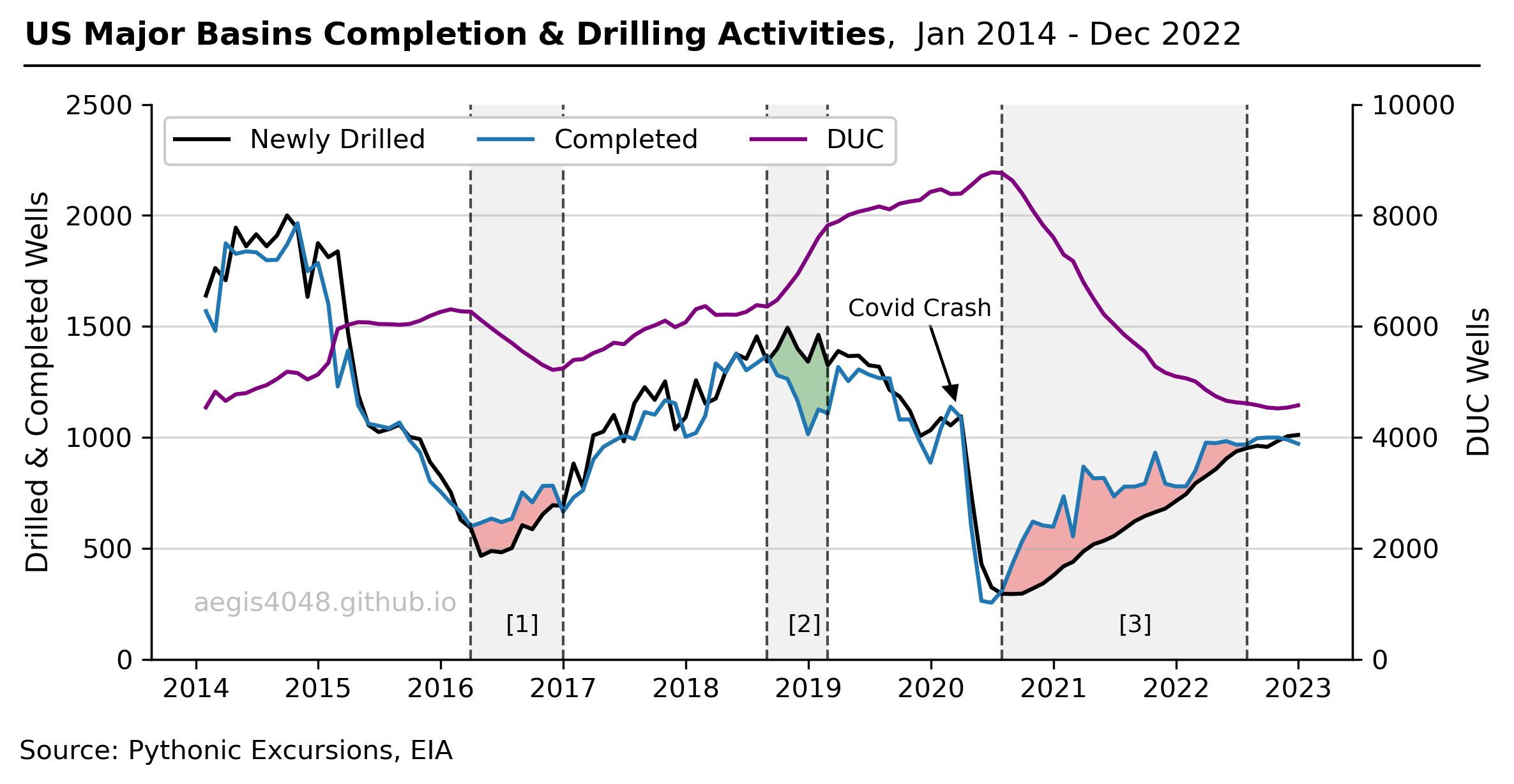
DUC Wells and Their Economic Complications
During the Covid-19 Pandemic, the operators opted not to drill new wells, but instead completed their existing DUC wells to meet demand while conserving cash. This post explains the concept and the economic impact of DUC wells on the US energy industry.
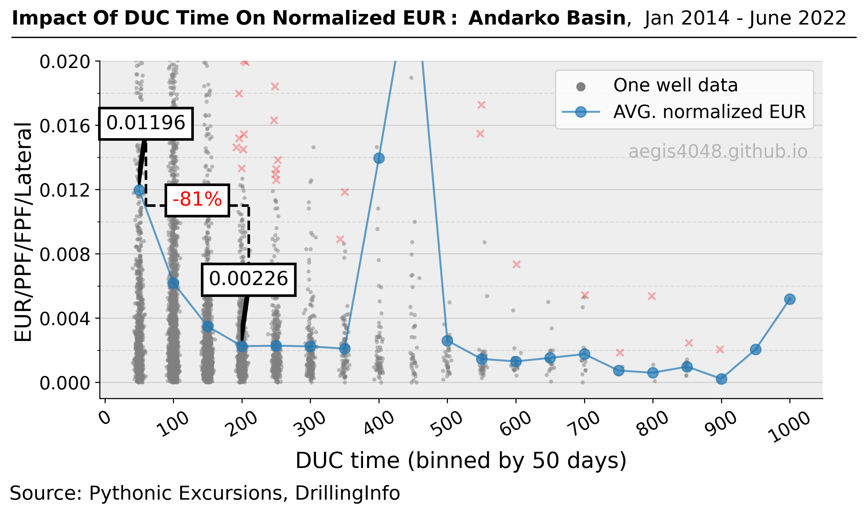
Quantifying The Impact Of Completion Delay Since Drilled On Production
In times of unfavorable commodity prices, operators may delay completion after drilling in the hope of a price recovery. The study conducted in this article shows why this may not be a financially sound idea for certain basins by quantifying the impact of DUC time on normalized EURs.
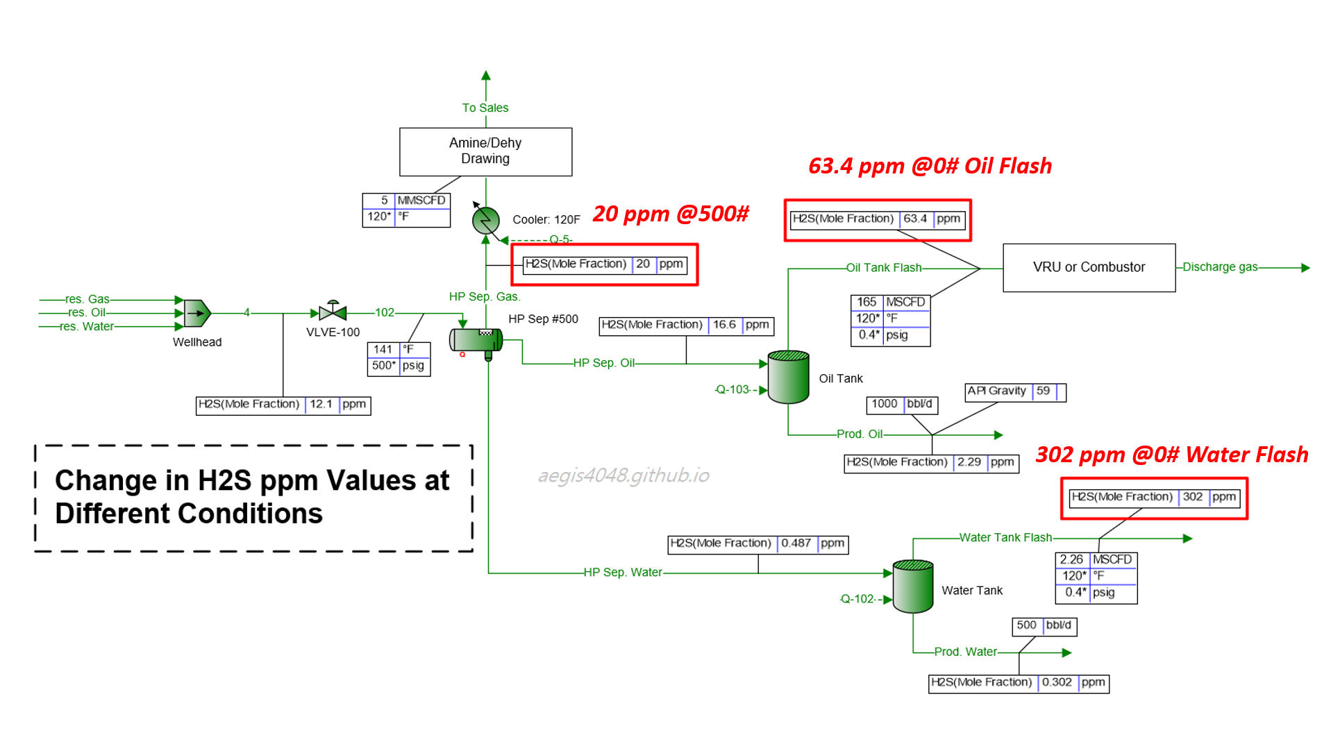
H₂S Levels: Why High-Pressure Samples Don't Tell the Full Story
H₂S ppm levels obtained from high pressure applications (HP separators) are often re-used for low pressure applications (atmospheric tanks). H₂S levels soar 3~25 times at low pressures. This post explains the thermodynamics behind H2S ppm level variations and provide simulation results summary for practical applications.
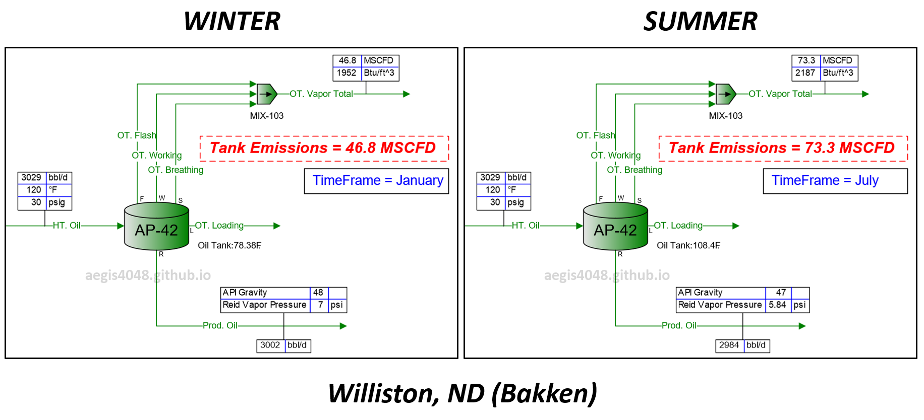
Impact of Seasonal Changes on Storage Tank Emissions
Storage tank temperatures rise in summer due to hot air, leading to higher emission volumes compared to winter. This temperature increase also impacts the dew point T, SG, and energy content (Btu/scf) of tank vapor. This post explains the phase behavior changes due to temperature shifts and provides a summary table with recommended operating capacity margins for emission handling systems across various regions.
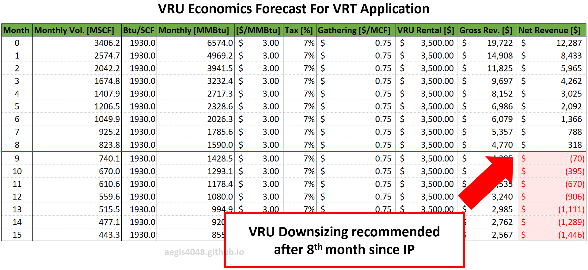
Predicting VRU Economics/Downsizing Timing For Declining Wells
Flash gas rates from low-pressure vessels (heaters, VRTs, and tanks) can decline much faster than anticipated, mirroring the rate of oil decline. In some cases, they can drop by half within just 3 to 6 months from IP. This post presents monthly process simulation results that model the decline of flash gas from low-pressure vessels as the well declines. An Excel sheet is also provided to help calculate VRU economics.